Design methodology for tissue engineering scaffolds and biomaterial implants

a tissue engineering and biomaterial technology, applied in the field of biomaterial scaffolds, can solve the problems of increasing reducing mechanical stiffness and strength, and presenting conflicting design requirements for the first two functions, and achieve optimal pore geometry and compute effective physical properties based on material microstructure.

Active Publication Date: 2007-02-06
HOLLISTER SCOTT J +2
View PDF12 Cites 294 Cited by
  • Summary
  • Abstract
  • Description
  • Claims
  • Application Information

AI Technical Summary

Problems solved by technology

Unfortunately, the first two functions present conflicting design requirements.
That is, increasing connected porosity to enhance cell migration and tissue regeneration decreases mechanical stiffness and strength.
Conversely, decreasing porosity increases mechanical stiffness and strength but impedes cell migration and tissue regeneration.
Unfortunately, this design approach fails to provide the ability to create optimal microstructures in an anatomical shape.
Also, this design approach fails to provide for the simultaneous design of a scaffold material property and the design of tissue structures in the scaffold pore space.
Finally, this design approach fails to allow for the design of both scaffold material and scaffold architecture.
Unfortunately, this design approach does not include any specific design method to create the interior of the implant.
Also, this design approach does not provide for optimized scaffold architectures with exterior anatomical shapes.
Finally, this approach relies upon computer aided design (CAD) techniques which are based on computational geometry entities like surfaces and splines that are not closely related to arbitrary, complex, anatomical geometries and cannot readily use the clinical imaging data that is the basis of creating an anatomically shape scaffold.
Unfortunately, the fabrication approach does not have the capability to optimize scaffold architecture and materials to attain natural tissue properties.
Although image data can be converted into geometric data, this does not allow for the design of arbitrary complex geometry.
Furthermore, CAD techniques do not allow for the combination of optimal scaffold architectures within many anatomical shapes.
Finally, the fabrication approach does not allow for the creation of designs by casting.

Method used


Image

  • Design methodology for tissue engineering scaffolds and biomaterial implants
  • Design methodology for tissue engineering scaffolds and biomaterial implants
  • Design methodology for tissue engineering scaffolds and biomaterial implants

Examples


Embodiment Construction

[0019]The following description of the preferred embodiment is merely exemplary in nature and is in no way intended to limit the invention, its application, or uses.

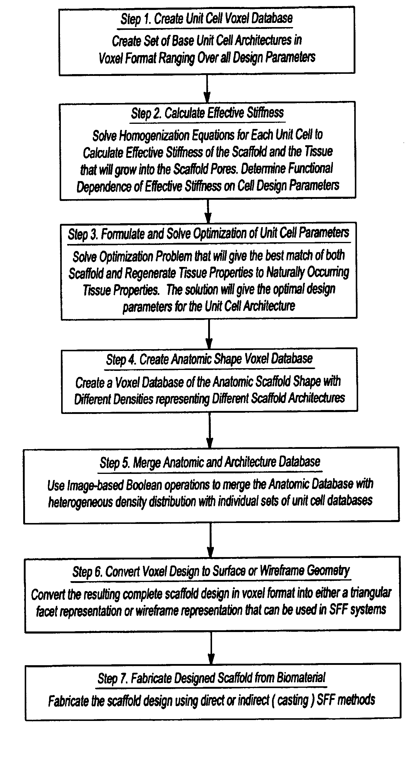
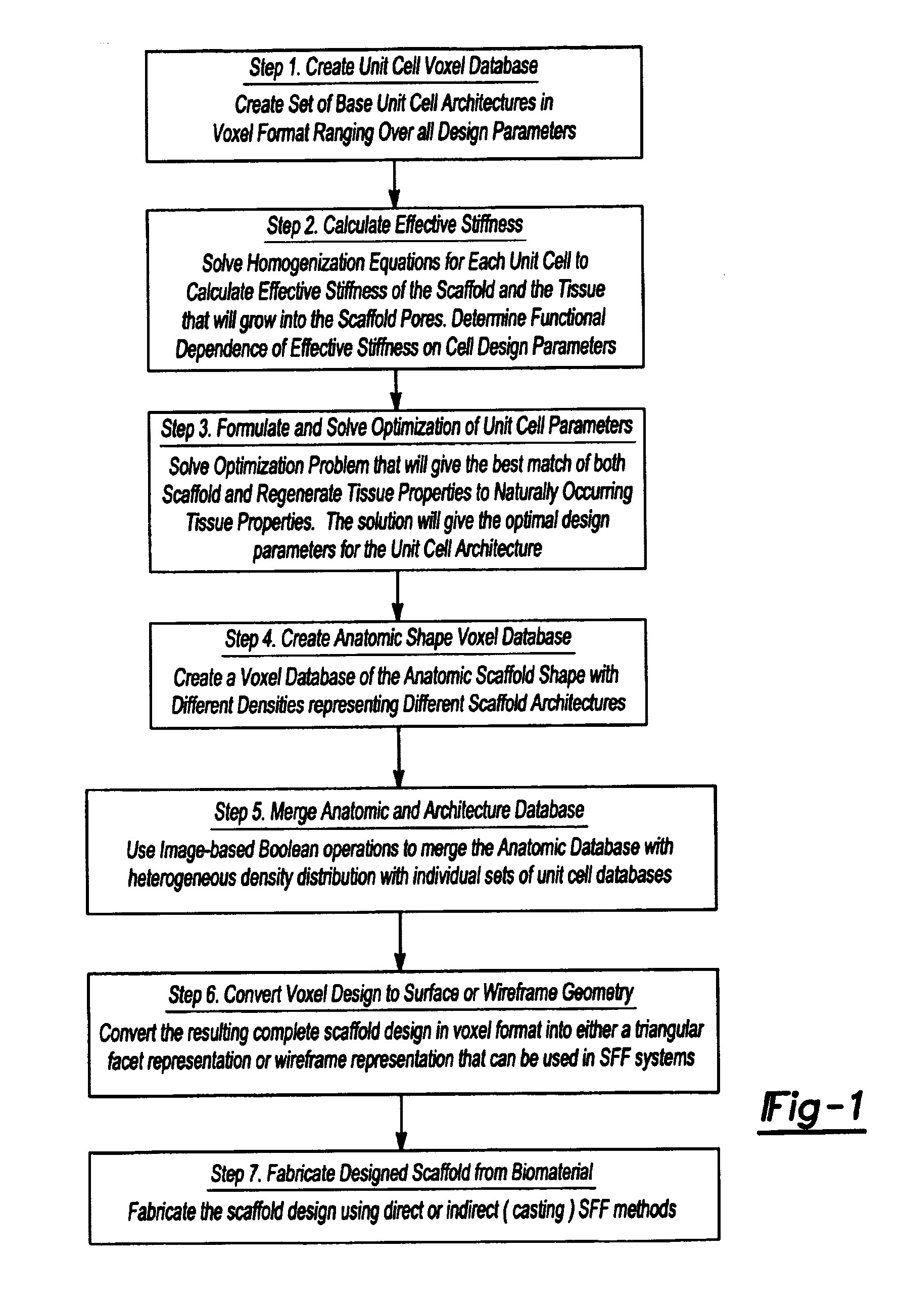
[0020]The present invention is generally directed towards a method approach for designing tissue engineering scaffolds, biomaterial implants, drug delivery systems, gene delivery systems and in vitro tissue testing systems that can be heterogeneously distributed to match any anatomic shape and can be fabricated using solid free form fabrication techniques. This invention incorporates image-based design techniques, homogenization theory, mathematical optimization algorithms, marching cubes and marching squares algorithms to convert image based design data to surface or wire frame geometry, and solid free form fabrication.

[0021]The steps for performing the scaffold optimization of the present invention are shown in FIG. 1. In step 1, the methodology creates unit cell voxel databases. That is, a set of base unit cell archit...


PUM

PropertyMeasurementUnit
diameteraaaaaaaaaa
porosityaaaaaaaaaa
Young's modulusaaaaaaaaaa

Abstract

A design methodology is provided for creating biomaterial scaffolds optimized for in vivo function with any 3D anatomic shape. The method creates all designs using voxel based design techniques. It also provides for optimization of implant and scaffold microstructure to best match functional and biofactor delivery (including cells, genes and proteins) requirements. The voxel based design techniques readily allow combination of any scaffold or implant microstructure database with any complex 3D anatomic shape created by CT or MRI scanners. These designs can be readily converted to formats for layered manufacturing or casting.

Description

CROSS-REFERENCE TO RELATED APPLICATIONS[0001]This application claims the benefit of U.S. Provisional Application No. 60 / 300,354, filed Jun. 22, 2001.FIELD OF THE INVENTION[0002]The present invention relates to biomaterial scaffolds and, more particularly, to a design methodology for tissue engineering scaffolds, biomaterial implants, gene therapy delivery systems, in vitro tissue testing systems and bioreactors, and drug delivery and testing systems.BACKGROUND OF THE INVENTION[0003]Biomaterial scaffolds for tissue engineering perform three primary functions. The first is to provide a temporary function (stiffness, strength, diffusion, and permeability) in tissue defects. The second is to provide a sufficient connected porosity to enhance biofactor delivery, cell migration and regeneration of connected tissue. The third requirement is to guide tissue regeneration into an anatomic shape.[0004]Unfortunately, the first two functions present conflicting design requirements. That is, incr...

Claims


Application Information

Patent Timeline
Patent Type & Authority Patents(United States)
IPC IPC(8): G06F17/10A61L27/56
CPCA61F2/28A61L27/56A61F2002/3092A61F2002/30952A61F2002/30948B33Y50/00
Inventor HOLLISTER, SCOTT JCHU, GABRIEL TIEN-MINTABOAS, JUAN M
Owner HOLLISTER SCOTT J
Why Eureka
Try Eureka