Refurbishing spent sputtering targets

a sputtering target and sputtering technology, applied in the field of sputtering target refurbishment, can solve the problem of high cost of sputtering material, and achieve the effect of reducing the amount of sputtering material needed

Inactive Publication Date: 2007-02-13
HERAEUS INC
View PDF12 Cites 64 Cited by
  • Summary
  • Abstract
  • Description
  • Claims
  • Application Information

AI Technical Summary

Benefits of technology

[0006]In the invention, the interface geometry between the support material and the sputter material is designed to minimize the amount of sputter material necessary for use in sputtering applications. The optimum design for the interface geometry corresponds to the natural sputter erosion groove or sputter profile of a spent sputtering target, which is created whi

Problems solved by technology

This is particularly important when

Method used


Image

  • Refurbishing spent sputtering targets
  • Refurbishing spent sputtering targets
  • Refurbishing spent sputtering targets

Examples


Embodiment Construction

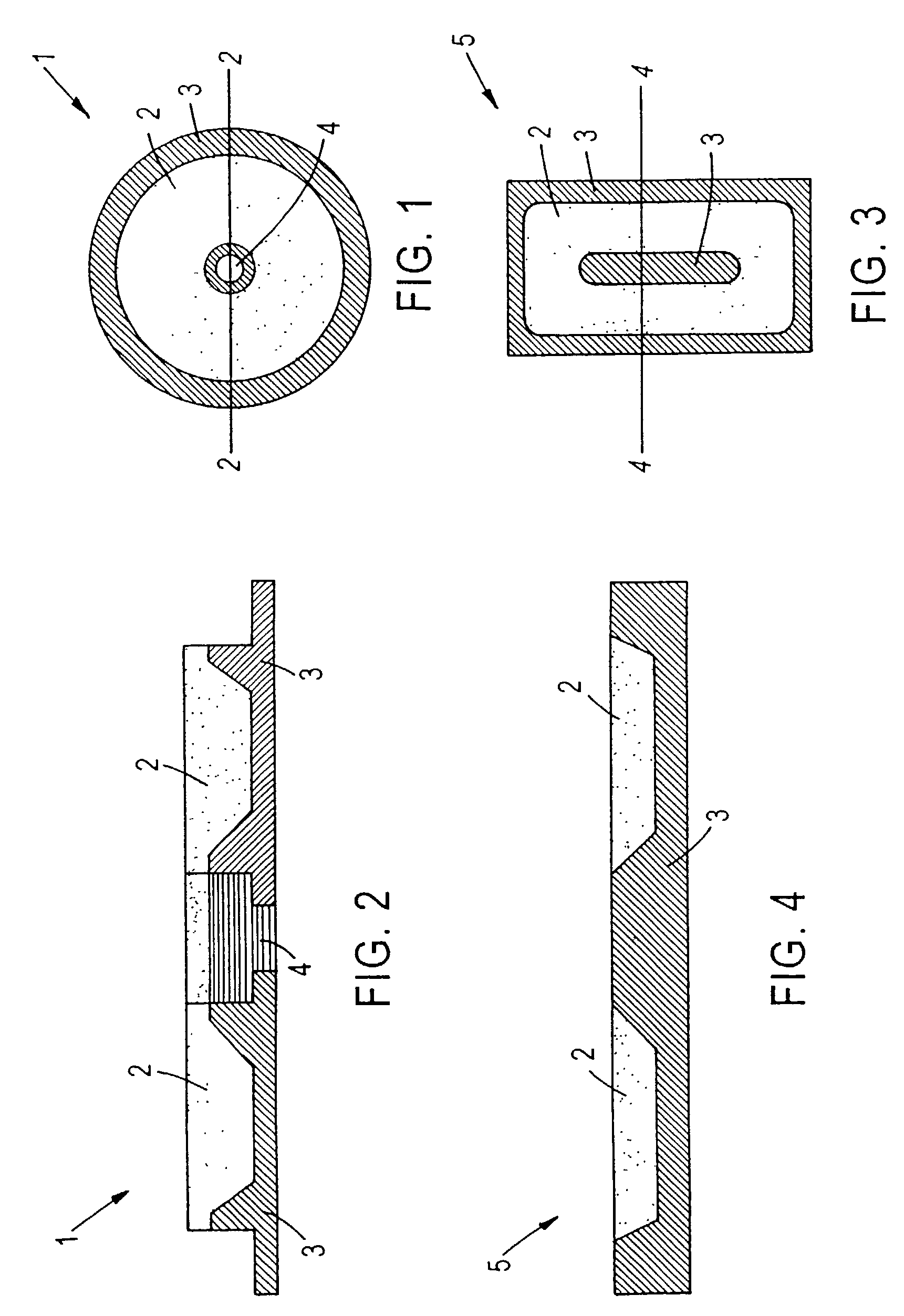
[0014]FIGS. 1 and 3 show typical geometries of the sputtering targets. FIG. 1 shows a disc shaped sputtering target having a circular sputter profile. In particular, the sputter material 2 is formed on a support structure 3. As illustrated in FIGS. 1 and 2, the target 1 is circular and donut shaped. The support structure 3 and sputter material 2 are concentric and are formed around hole 4 in the center of the target. Also, the sputtering target can be rectangular in shape as shown in FIGS. 3 and 4 where the sputtering target 5 has a profile that is rectangular.

[0015]The support structure 3 can be a material selected from the group consisting of Cu, CoCr alloy, stainless steel, NiAl alloy, W, Mo, CoCrPtB alloy, or RuAl alloy and PtMn alloy. The sputter material 2 can be a magnetic or non-magnetic material such as an alloy containing Co, Cr, Cu, Ni, Al, Mo, Pt, Ru, Pd, Re, Rh, Au or Ag metal. Examples of such alloys include RuAl and PtMn. The new sputter material is diffusion bonded t...


PUM

PropertyMeasurementUnit
Magnetismaaaaaaaaaa

Abstract

Spent sputtering targets are refurbished by filling the depleted region of the target with new sputter material using a hot isostatic pressing or HIP'ing technique.

Description

RELATED APPLICATIONS[0001]This application claims the benefit of U.S. provisional application No. 60 / 322,429, entitled “REFURBISHING SPENT SPUTTERING TARGETS” filed on Sep. 17, 2001 by Michael Sandlin, the disclosure of which is incorporated herein by reference.FIELD OF THE INVENTION[0002]The invention is directed to refurbishing a spent sputtering target. The target is refurbished by filling an erosion groove in the spent sputtering target with new sputter material that was depleted during the sputtering process. As a result, the spent sputtering target is reprocessed.BACKGROUND OF THE INVENTION[0003]Cathodic sputtering is widely used for the deposition of thin layers of material onto desired substrates. A typical sputtering system includes a plasma source for generating an electron or ion beam, a target that comprises a material to be atomized, and a substrate onto which the sputtered material is deposited. The process involves bombarding the target material with the electron or i...

Claims


Application Information

Patent Timeline
IPC IPC(8): C23C14/34B22F7/00B22F7/06G11B5/851
CPCB22F7/062C23C14/3414B22F2007/068B22F2998/10B22F3/1208B22F3/15C23C14/34
Inventor SANDLIN, MICHAELZHANG, WENJUNKUNKEL, BERND
Owner HERAEUS INC
Why Eureka
Try Eureka