Exposure apparatus and method

a technology which is applied in the field of exposure apparatus and exposure method, can solve the problems of deteriorating alignment accuracy, affecting the accuracy of alignment, and affecting the effect of accuracy, so as to achieve the effect of improving throughput and easy changing

Inactive Publication Date: 2007-02-13
NIKON CORP
View PDF82 Cites 139 Cited by
  • Summary
  • Abstract
  • Description
  • Claims
  • Application Information

AI Technical Summary

Benefits of technology

[0133]The controller is capable of controlling the operations of the two stages as follows. That is, the position of the first substrate stage is managed without any Abbe error with respect to the sensitive substrate held on the first substrate stage, based on the use of the measured value obtained by using the third length-measuring axis which perpendicularly intersects the length-measuring axes (the first length-measuring axis and the second length-measuring axis) in the first axis direction at the projection center of the projection optical system, while the image of the pattern formed on the mask is subjected to exposure through the projection optical system, during which the positional relationship between the alignment mark on the sensitive substrate held on the second substrate stage and the reference mark on the second substrate stage is accurately detected without any Abbe error based on the use of the detection result obtained by using the mark detecting system and the measured value obtained by using the fourth length-measuring axis which perpendicularly intersects the length-measuring axes (the first length-measuring axis and the second length-measuring axis) in the first axis direction at the detection center of the mark detecting system. Accordingly, it is possible to concurrently perform the exposure operation effected on the one substrate stage and the alignment operation effected on the second substrate stage as described above.
[0134]Then, the controller controls the operation of the first substrate stage as follows. That is, when the above-mentioned operations of the both stages are completed, the position of the first substrate stage is measured by the measured value obtained by using the fifth length-measuring axis, while obtaining the relative position between the detection center of another mark detecting system and the reference mark on the first substrate stage. Accordingly, as for the first substrate stage for which the exposure for the sensitive substrate has been completed, the position of the first substrate stage can be managed without any Abbe error, based on the use of the reference mark on the first substrate stage and the measured value obtained by using the fifth length-measuring axis. Further, there is no inconvenience, even when the third length-measuring axis used during the exposure falls

Problems solved by technology

As a result, if a shot having a size equivalent to a shot size of the stepper is exposed, there is a possibility that the throughput is rather decreased as compared with the stepper.
However, on the contrary, the alignment accuracy is deteriorated due to shortened T3.
Therefore, it is impossible to easily shorten T3.
However, it is not allowed to increase the scanning velocity without consideration because the synchronization accuracy is deteriorated.
With the apparatus using an off-axis alignment microscope, such as the projection exposure apparatus with the excimer laser light source which would be predominant in this field, it is not easy to improve the controllability of the stage.
However, the case of the ArF excimer laser involves numerous technical problems in that the light is scarcely transmitted through a place where oxygen exists, it is difficult to provide a high output, the service life of the laser is short, and the cost of the apparatus is expensive.
The electron beam exposure apparatus is inconvenient in that the throughput is extremely low as compared with the light beam exposure apparatus.
In reality, the development of the next generation machine, which is based on the principal viewpoint of the use of a short wavelength, does not proceed so well.
It is conceived to increase the numerical aperture N.A., as another

Method used


Image

  • Exposure apparatus and method
  • Exposure apparatus and method
  • Exposure apparatus and method

Examples


first embodiment

[First Embodiment]

[0277]A first embodiment of the present invention will be explained below with reference to FIGS. 1 to 18.

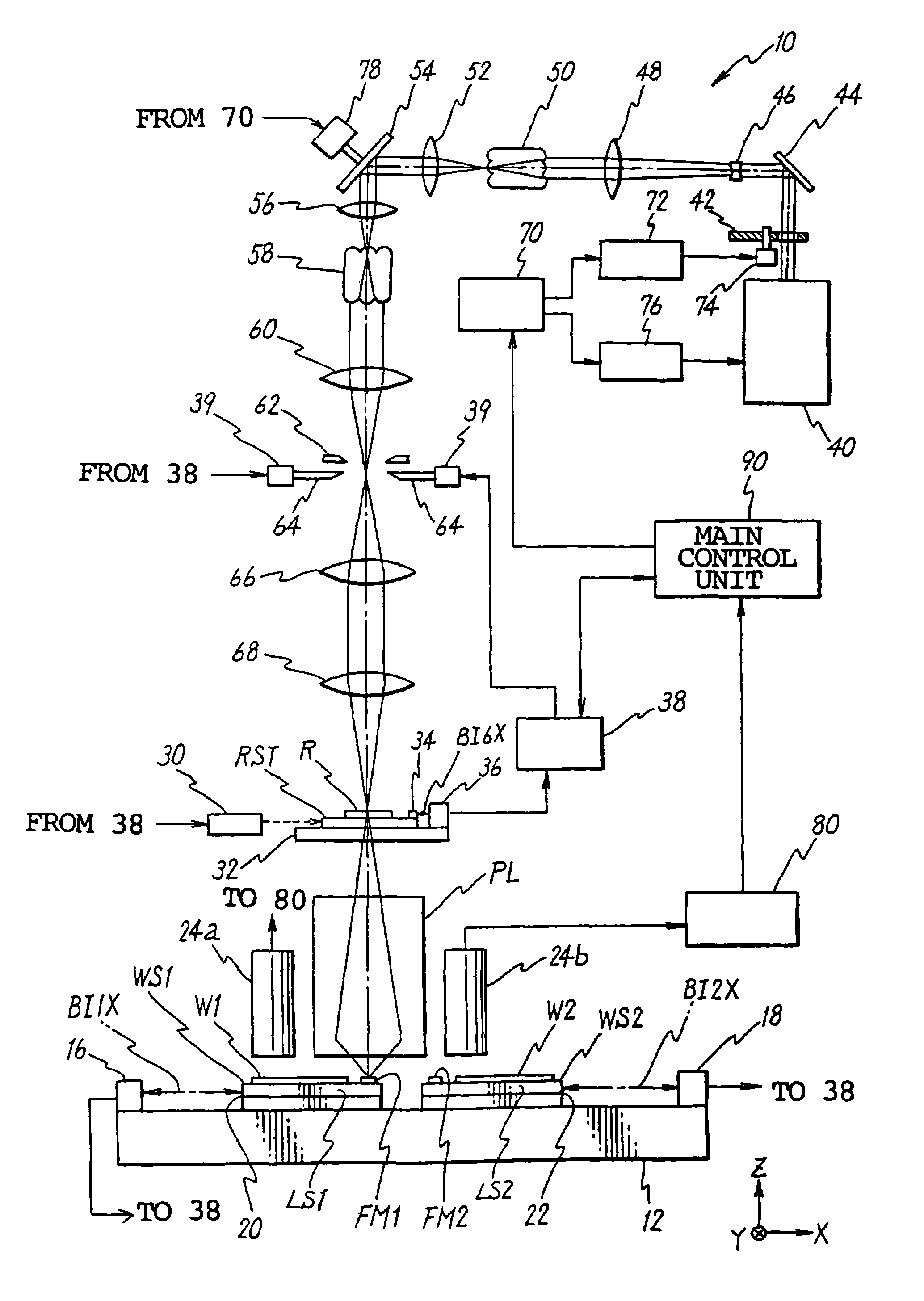
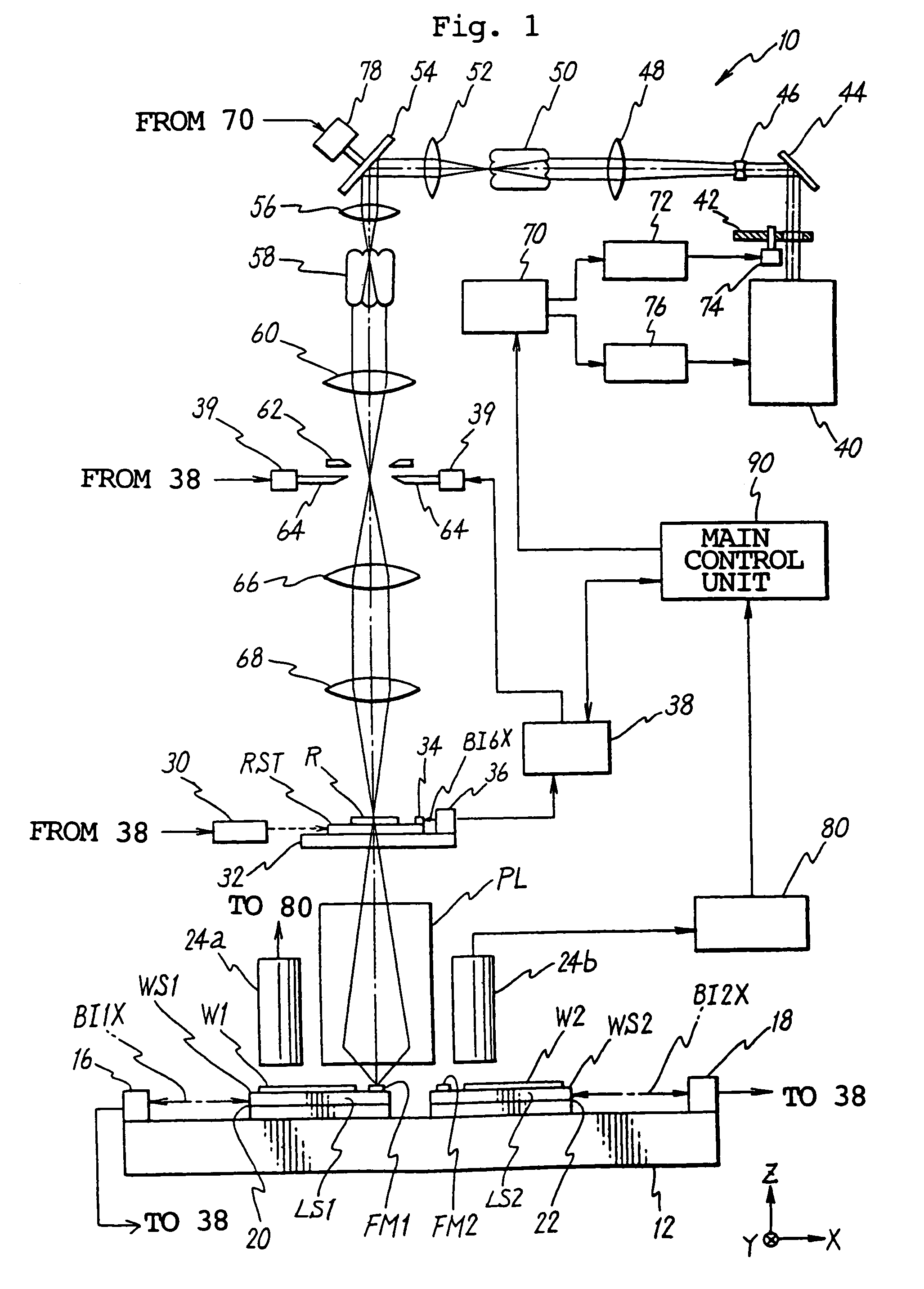
[0278]FIG. 1 shows a schematic arrangement of a projection exposure apparatus 10 according to the first embodiment. The projection exposure apparatus 10 is a projection exposure apparatus of the scanning exposure type based on the so-called step-and-scan system. A structure and a controlling method of the step-and-scan system projection exposure apparatus are disclosed in U.S. Pat. Nos. 5,646,413 and 5,448,332, the disclosures of which are herein incorporated by reference.

[0279]The projection exposure apparatus 10 comprises, for example, a stage apparatus provided with wafer stages WS1, WS2 as first and second substrate stages which are independently movable in the two-dimensional direction on a base pedestal 12 while holding wafers W1, W2 as sensitive substrates, a projection optical system PL disposed over the stage apparatus, a reticle-driving mechanism disp...

second embodiment

[Second Embodiment]

[0399]Next, the second embodiment of the present invention will be explained with reference to FIGS. 22 and 23. In this embodiment, constitutive components which are the same as or equivalent to those referred to in the first embodiment described above are designated by the same reference numerals, explanation of which is simplified or omitted.

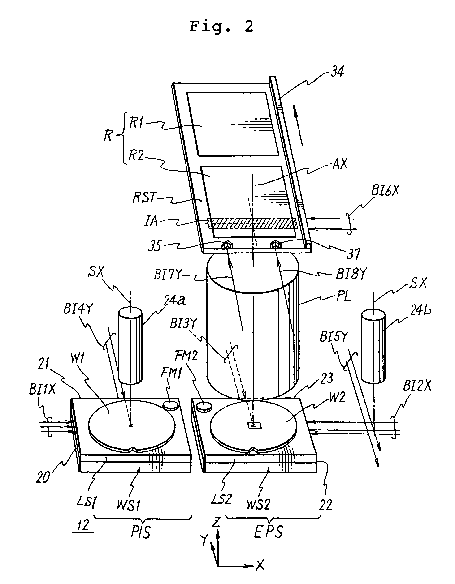
[0400]As shown in FIG. 22, a projection exposure apparatus according to the second embodiment is characterized in that the length-measuring beam BI4Y (or BI5Y) is not deviated from the reflective surface of the stage during the movement of the wafer stage WS1 (or WS2) from the completion position of the alignment sequence to the start position of the exposure sequence, because the length of one side of the wafer stage WS1 (the length of one side of WS2 is identical thereto) is longer than the mutual distance BL between the length-measuring axes BI4Y and BI3Y (the mutual distance between the length-measuring axes BI5Y and BI3...

third embodiment

[Third Embodiment]

[0415]In the first embodiment of the present invention, the different operations are concurrently processed in parallel to one another by using the two wafer stages WS1, WS2. Therefore, there is a possibility that the operation performed on the one stage gives influence (disturbance) to the operation of the other stage. For this reason, as described above, it is necessary to adjust the timing for the operations performed on the two stages WS1, WS2.

[0416]In this embodiment, explanation will be made for the timing adjustment for the operations performed on the two stages WS1, WS2, with reference to FIGS. 11, 12 and 24.

[0417]As explained in the first embodiment, FIG. 11 shows an example of the timing of the exposure sequence for successively exposing the respective shot areas on the wafer W1 held on the stage WS1. FIG. 12 shows the timing of the alignment sequence for the wafer W2 held on the stage WS2, which is processed concurrently in parallel thereto.

[0418]As desc...


PUM


Abstract

A scanning exposure apparatus includes a projection system, a stage system, a first detector and a control system. The stage system has first and second stages, each of which is movable independently in a plane while holding a substrate. The first detector detects focusing information of a vicinity of an outer circumference of the substrate during a detecting operation. The control system controls the stage system to perform the detecting operation with the first stage, while performing a first exposure operation on the substrate held by the second stage. After the first exposure operation, a second exposure operation for the substrate held on the first stage is performed, in which a shot area in the vicinity of the outer circumference of the substrate is exposed by moving the first stage while adjusting a position of the substrate surface held by the first stage using the detected focusing information.

Description

[0001]This a Division of application Ser. No. 10 / 024,147 filed Dec. 21, 2001 now U.S. Pat. No. 6,798,491, which in turn is a Division of application Ser. No. 09 / 666,407 filed Sep. 20, 2000 (now U.S. Pat. No. 6,400,441), which in turn is a Continuation of application Ser. No. 08 / 980,315 filed Nov. 28, 1997 (now abandoned), which claims the benefit of the following five (5) Provisional Applications: U.S. Provisional Application No. 60 / 059,989 filed Sep. 25, 1997, U.S. Provisional Application No. 60 / 059,992 filed Sep. 25, 1997, U.S. Provisional Application No. 60 / 060,022 filed Sep. 25, 1997, U.S. Provisional Application No. 60 / 060,076 filed Sep. 25, 1997 and U.S. Provisional Application No. 60 / 060,677 filed Sep. 25, 1997. The entire disclosure of the prior applications is incorporated herein by reference in their entireties.FIELD OF THE INVENTION[0002]The present invention relates to an exposure apparatus and an exposure method for exposing a sensitive substrate with a laser beam, an e...

Claims


Application Information

Patent Timeline
IPC IPC(8): G03B27/42H01L21/027G03F7/20G03F9/00
CPCG03F7/70216G03F7/70358G03F7/70425G03F7/70716G03F9/7088G03F9/70G03F9/7003G03F9/7015G03F9/7026G03F7/70733H01L21/027
Inventor NISHI, KENJIOTA, KAZUYA
Owner NIKON CORP
Why Eureka
Try Eureka