
Method for calculating toner age and a method for calculating carrier age for use in print engine diagnostics

a technology of toner age and carrier age, which is applied in the field of copying or digital imaging system, can solve the problems of poor development of solid areas, affect the relationship between tc and developability, and visible defects in mono-color images, and achieve the effect of robustness against errors

Inactive Publication Date: 2007-02-13
XEROX CORP
View PDF7 Cites 19 Cited by
  • Summary
  • Abstract
  • Description
  • Claims
  • Application Information

AI Technical Summary

Benefits of technology

[0003]With the increase in use and flexibility of printing machines, especially color printing machines which print with two or more different colored toners, it has become increasingly important to monitor the toner development process so that increased print quality, stability and control requirements can be met and maintained. For example, it is very important for each component color of a multi-color image to be stably formed at the correct toner density because any deviation from the correct toner density may be visible in the final composite image. Additionally, deviations from desired toner densities may also cause visible defects in mono-color images, particularly when such images are half-tone images. Therefore, many methods have been developed to monitor the toner development process to detect present or prevent future image quality problems.
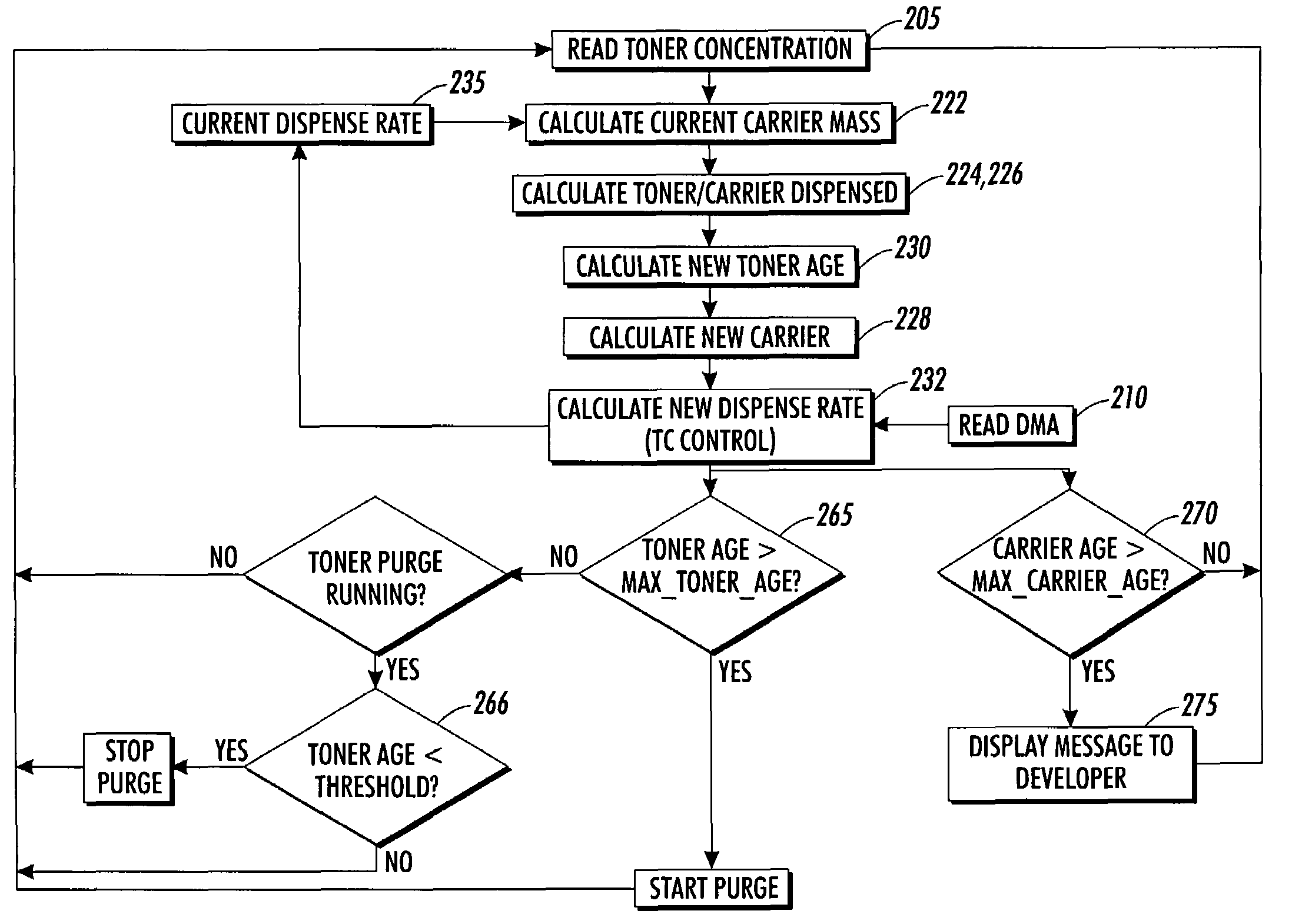
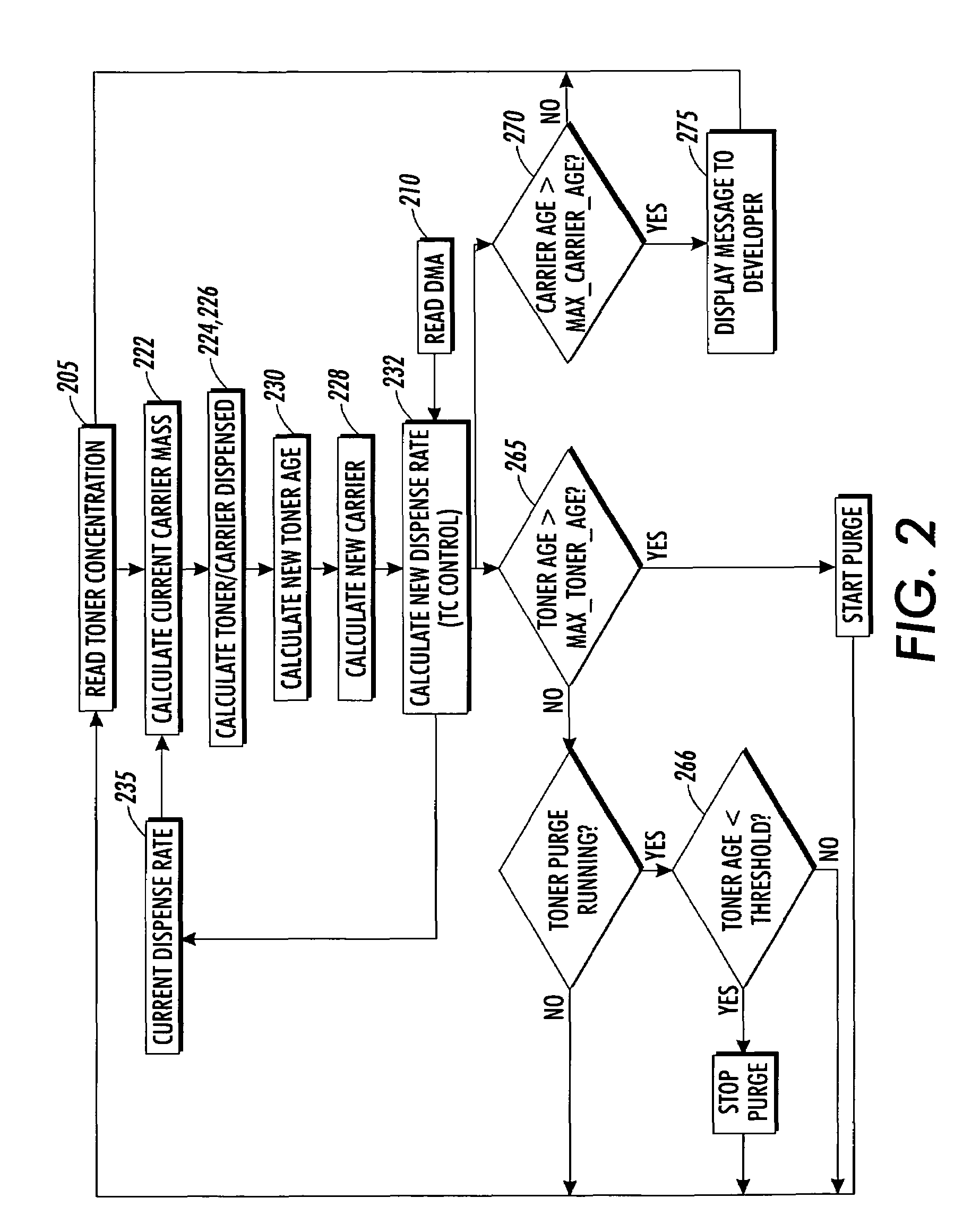
[0010]There is provided a method for estimating both toner age and carrier age based on measuring the amount of replenisher actually dispensed. This method is robust against errors which can arise from using pixel count as the basis for estimating the toner age or carrier age. In image-on-image development systems, the developed mass per unit area will depend on whether the developed toner is deposited directly on the photoreceptor or is deposited on toner developed in previous steps. Thus the average developed toner mass per unit area (dma) will depend on the image content, and thus be prone to error. These errors are compounded further by non-linear half toning effects. As an example, a 10% halftone will require developing 1 / 10th the available pixels in a given area, but the amount of toner developed under the same conditions used to develop the solid will, in general not be 10% of the amount required to develop all the pixels in that area. This departure from proportionality to the fraction of pixels developed will change with the proportion of pixels and may change with selected print conditions, such as darkness or lightness control settings. Additionally, the pixel count cannot account for non-printing toner usage such as emissions or while adding toner without developing (a tone-up process). A properly calibrated system for dispensing toner or replenisher material into a developer housing to replace the material removed provides an alternate and improved method for measuring toner age. In addition, it does not require the additional electronic circuitry associated with counting pixels. Because a pixel count is not used, the invention is also applicable to copiers and similar devices which do not have digital images.

Problems solved by technology

Additionally, deviations from desired toner densities may also cause visible defects in mono-color images, particularly when such images are half-tone images.
However, the relationship between TC and developability is affected by other variables such as ambient temperature, humidity and the age of the toner.
When carriers which are used in conductive or semiconductive magnetic brush development systems become encased in toner resin fines they may become too insulative to function properly, leading to poor development of solid areas.
Alternatively, coatings on the carrier which are present to provide proper tribocharging of the toner, can wear off with the result that the carrier no longer functions as intended.
Thus the average developed toner mass per unit area (dma) will depend on the image content, and thus be prone to error.
These errors are compounded further by non-linear half toning effects.
Additionally, the pixel count cannot account for non-printing toner usage such as emissions or while adding toner without developing (a tone-up process).

Method used


Image

  • Method for calculating toner age and a method for calculating carrier age for use in print engine diagnostics
  • Method for calculating toner age and a method for calculating carrier age for use in print engine diagnostics
  • Method for calculating toner age and a method for calculating carrier age for use in print engine diagnostics

Examples


Embodiment Construction

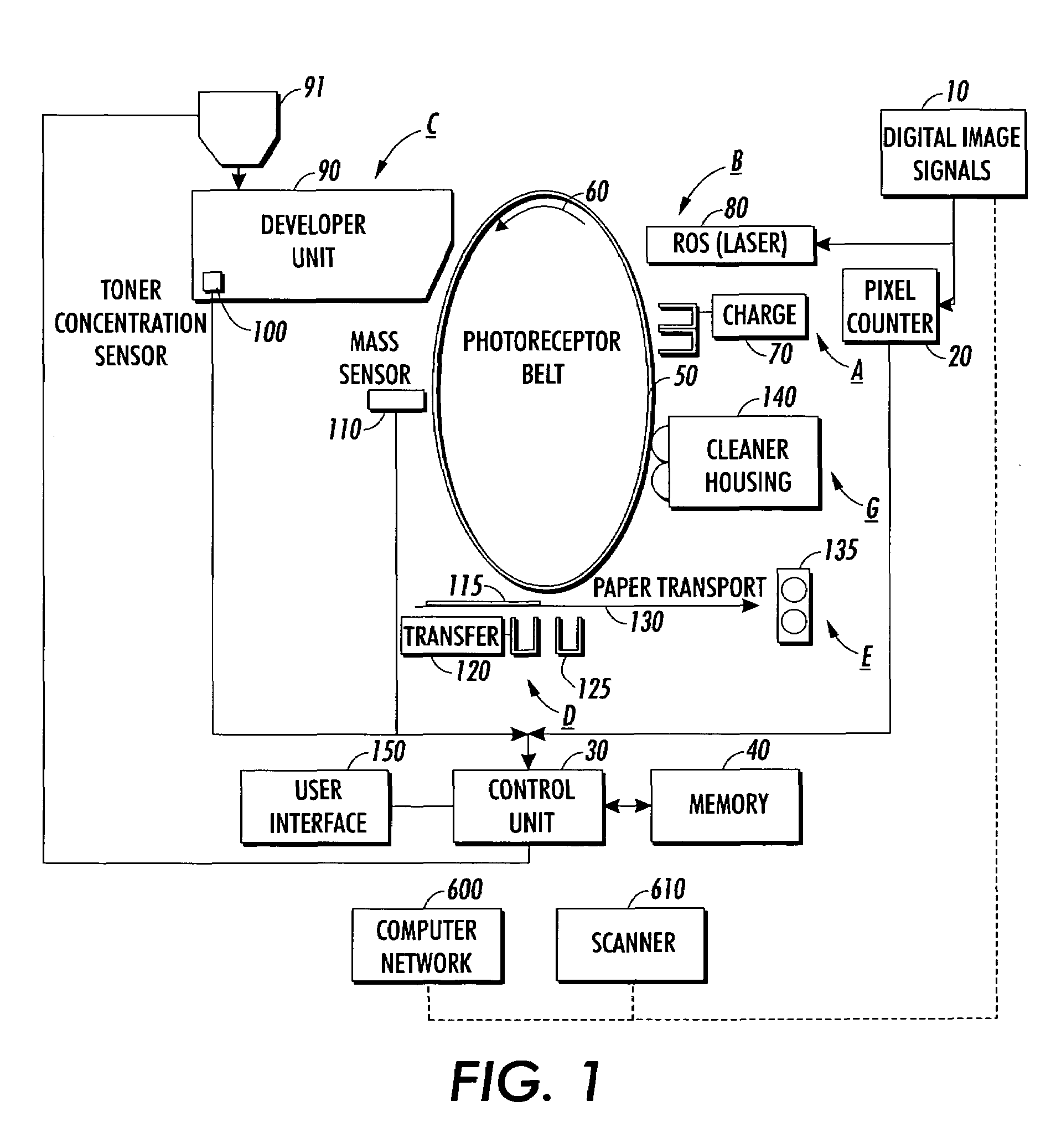
[0017]FIG. 1 shows a partial schematic of an example of a print engine for a digital imaging system. Digital image signals 10 from a computer network 600, scanner 610, or other digital image signal generating device are received by a pixel counter 20, which counts the number of pixels in the digital image. The digital image signals 10 represent the desired output image to be imparted on at least one sheet or in one non-printing area. The pixel counter 20 outputs this information to a control unit 30, which stores this information in memory 40. The control unit 30 may be a microprocessor or other control device. The pixel counter 20 may be incorporated into the control unit 30.

[0018]A photoreceptor belt 50 advances sequentially through various xerographic process stations in the direction indicated by arrow 60. Other types of photoreceptors such as a photoreceptor drum may be substituted for the photoreceptor belt 50 for sequentially advancing through the xerographic process stations...


PUM


Abstract

The present invention generally relates to a digital imaging system or a light lens based imaging system. More specifically, the present invention provides an improved method and apparatus for calculating toner age and, additionally, carrier age using a toner concentration sensor and the amount of material dispensed. Both of these quantities can be used to ensure image quality by anticipating or diagnosing problems in image quality, which may be caused by toner age or carrier age.

Description

FIELD OF THE INVENTION[0001]The present invention generally relates to a copier or digital imaging system. More specifically, the present invention provides an improved method for calculating toner age and for calculating carrier age to ensure image quality by anticipating or diagnosing problems in image quality, which may be caused by toner age or carrier age. These problems include low developability, high background, light or incompletely developed solid areas, and halo defects appearing on sheets of support material.BACKGROUND AND SUMMARY[0002]Modern electronic copiers, printers, facsimile machines, etc. are capable of producing complex and interesting page images. The pages may include text, graphics, and scanned or computer-generated images. The image of a page may be described as a collection of simple image components or primitives (characters, lines, bitmaps, colors, etc.). Complex pages are built from these primitives using a page description language such as PostScript. T...

Claims


Application Information

Patent Timeline
Patent Type & Authority Patents(United States)
IPC IPC(8): G03G15/08G03G21/00
CPCG03G15/0848G03G15/0844
Inventor KRECKEL, DOUGLAS A.
Owner XEROX CORP
Learn More