Unlock instant, AI-driven research and patent intelligence for your innovation.

Remote control system, remote control apparatus, remote control method, program for implementing the method, and electronic apparatus

a remote control and remote control technology, applied in the field of remote control systems and remote control apparatuses, can solve the problems of difficult use of remote controllers, high possibility of infrared light signal for catv, excessive key pressing, etc., and achieve the effect of reliable provision of desired control and saving power

Inactive Publication Date: 2007-02-13
CANON KK
View PDF6 Cites 15 Cited by
  • Summary
  • Abstract
  • Description
  • Claims
  • Application Information

AI Technical Summary

Benefits of technology

[0020]It is a first object of the present invention to provide a remote controller system, a remote controller apparatus, and a remote controller method, which can reliably provide desired control while saving power, as well as to a program for implementing the method and an electronic apparatus which is remotely controlled.
[0021]It is a second object of the present invention to provide a remote controller system, a remote controller apparatus, and a remote controller method, which can reliably provide desired control even if the electronic apparatus has failed to receive part of a control signal which is repeatedly transmitted during the depression of a key, as well as to a program for implementing the method and an electronic apparatus which is remotely controlled.
[0023]According to the first aspect of the present invention, it is possible to reliably provide desired control while saving power.
[0040]According to the twelfth aspect of the present invention, it is possible to reliably provide desired control even if the electronic apparatus has failed to receive part of a control signal which is repeatedly transmitted during the depression of a key.

Problems solved by technology

H08-163531, a signal is transmitted from the remote controller only once or twice, and hence the CATV can fail to receive an infrared light signal with a high possibility, and the same problem arises as in the case where the repeat code 306 is used.
In either case, the operator of the remote controller misbelieves that the remote controller or the apparatus to be controlled has failed since the apparatus to be controlled does not operate in response to the depression of a key, or misbelieves that an intended key of the remote controller has not yet been turned on, and therefore continuously depresses the key with an excessive force, and therefore the remoter controller is not easy to use.
However, in the case of a key such as a channel switch key for a TV set or a video signal input switch key other than a key used for e.g. volume control which requires an instruction for continuous operation, a control signal is continuously transmitted although the control signal does not have to be repeatedly transmitted even if the key is continuously depressed (this also applies to the case where the repeat code 306 is transmitted), and this wastes a battery for the remote controller.
In this case, however, since one signal is transmitted for only a short period of time, i.e. about several 10 ms as described above, the apparatus to be controlled can fail to receive a control signal with a high possibility in the environment where there are a large amount of fluorescent light of a fluorescent lamp or other disturbance light.
In this case, as described above, the operator of the remote controller misbelieves that the remote controller or the apparatus to be controlled has failed since the apparatus to be controlled does not operate in response to the depression of the key, or misbelieves that an intended key switch for the remote controller has not yet been turned on, and therefore, should continuously depress the key with an excessive force.
Therefore, the remote controller is not easy to use.

Method used


Image

  • Remote control system, remote control apparatus, remote control method, program for implementing the method, and electronic apparatus
  • Remote control system, remote control apparatus, remote control method, program for implementing the method, and electronic apparatus
  • Remote control system, remote control apparatus, remote control method, program for implementing the method, and electronic apparatus

Examples


first embodiment

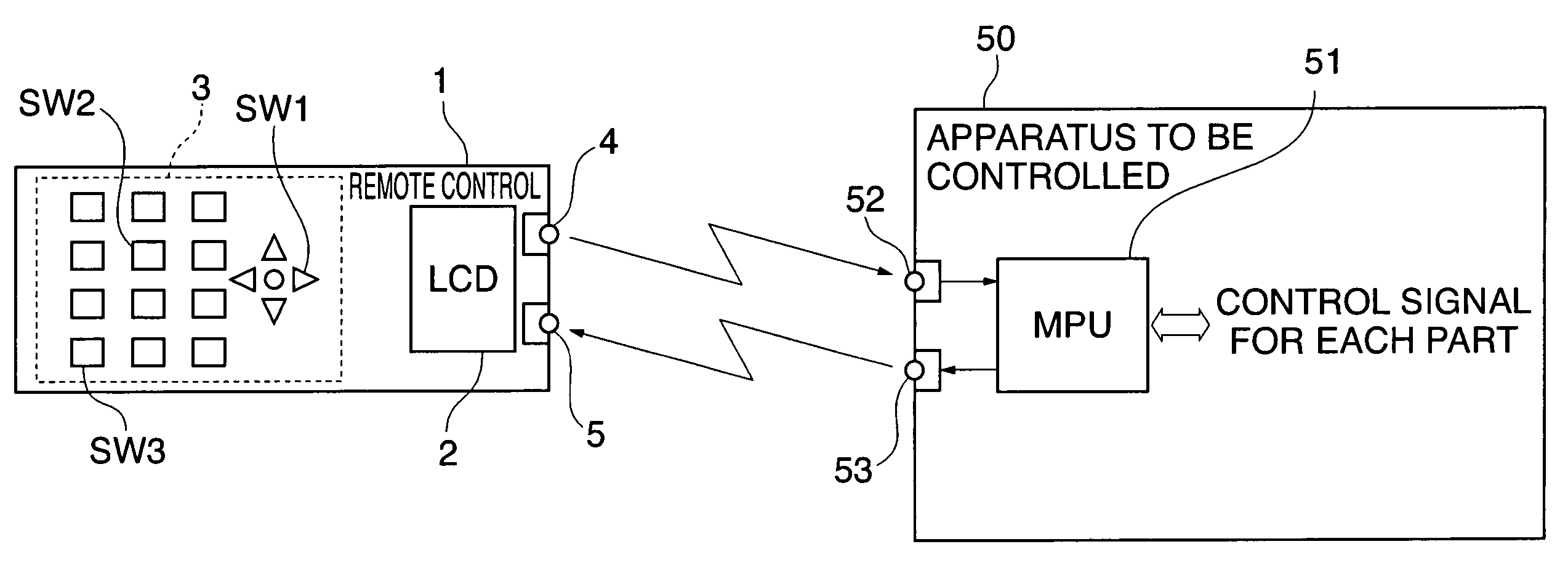
[0073]FIG. 1 is a view showing the arrangement of a remote control system according to the present invention. In FIG. 1, reference numeral 1 denotes a remote controller, and reference numeral 50 denotes an apparatus to be controlled.

[0074]The remote controller 1 includes a keyboard 3, a liquid crystal display 2, an infrared light emitting section (infrared light emitting diode) 4, and an infrared light receiving section (photodiode) 5. The apparatus 50 to be controlled (hereinafter referred to as the “controlled apparatus 50”) includes an infrared light receiving section 52 for receiving an infrared light signal from the remote controller 1, an infrared light emitting section 53 for transmitting an infrared light signal to the remote controller 1, and a microprocessor (MPU) 51 which controls processing of the transmitted and received signals and component parts, not shown, of the controlled apparatus 50.

[0075]FIG. 2 is a view showing the arrangement of a conventional remote control ...

second embodiment

[0124]A description will now be given of the present invention.

[0125]In the above described first embodiment, if a key is continuously depressed, the packet number “00” is assigned to the first light signal, and the packet numbers “01”, “10”, “11”, “01” . . . are cyclically assigned to the second and subsequent light signals, but in the second embodiment, a packet number “01” is fixedly assigned to the second and subsequent light signals although a packet number “00” is assigned to the first signal as is the case with the first embodiment.

[0126]FIG. 10 is a view schematically showing a procedure for carrying out communication between the remote controller 1 according to the second embodiment and the controlled apparatus 50. When an arbitrary key switch SW2 of the remote controller 1 (refer to FIG. 1) is depressed, an infrared light signal 1101 with the format in FIG. 5 is transmitted. If normally receiving the infrared light signal 1101, the controlled apparatus 50 returns a return ...

third embodiment

[0132]A description will now be given of the present invention.

[0133]One frame of a light signal transmitted from the remote controller 1 is formatted as shown in FIG. 5 according to the first and second embodiments, but is formatted as shown in FIG. 11 according to the third embodiment.

[0134]In FIG. 11, reference numeral 1201 denotes a leader code; 1202, a custom code; 1203, a host number; 1204, a remote controller number; 1205, a communication type code indicative of whether data to be transmitted is comprised of one frame or a plurality of frames; 1206, a data length code indicative of the length of data (command) 1207; 1207, data (command); 1208, a check sum; and 1209, an END code.

[0135]Specifically, the frame of a light signal according to the third embodiment is configured by removing a packet number from the frame of a light signal according to the first and second embodiments.

[0136]FIGS. 12A and 12B are views showing examples of the driving waveform of the leader code 1201 i...


PUM


Abstract

A remote control system which can reliably provide desired control while saving power. A remote control apparatus is capable of carrying out two-way wireless communication with an apparatus to be controlled. A control signal corresponding to a key switch for remote control is repeatedly transmitted while the key switch is being operated. Repeated transmission of the control signal is inhibited in accordance with reception of a predetermined signal from the apparatus to be controlled.

Description

BACKGROUND OF THE INVENTION[0001]1. Field of the Invention[0002]The present invention relates to a remote control system, a remote control apparatus, and a remote control method, which carry out remote control (remote operation) of an electronic apparatus by means of e.g. infrared light, as well as to a program for implementing the method and an electronic apparatus which is remotely controlled. In particular, the present invention relates to a remote control system, a remote control apparatus, and a remote control method, which carry out remote control of an electronic apparatus by sequentially transmitting control signals for providing predetermined control, as well as to a program for implementing the method and an electronic apparatus which is remotely controlled.[0003]2. Description of the Related Art[0004]Conventionally, in a remote control apparatus (hereinafter referred to as “the remote controller”) which remotely controls an electronic apparatus such as a television set or...

Claims


Application Information

Patent Timeline
Patent Type & Authority Patents(United States)
IPC IPC(8): H04M3/00H04B1/06H04B1/16H04B1/20
CPCH04B1/202Y02B60/50H04W52/0225Y02D30/70
Inventor ISHIWATARI, MASUMI
Owner CANON KK
Features
  • R&D
  • Intellectual Property
  • Life Sciences
  • Materials
  • Tech Scout
  • Unparalleled Data Quality
  • Higher Quality Content
  • 60% Fewer Hallucinations
Learn More