
Filter/emboli extractor for use in variable sized blood vessels

a filter and extractor technology, applied in the field of medical devices, can solve the problems of myocardial infarction, stroke or even death, morbidity and mortality, tissue ischemia (lack of oxygen and nutrients),

Inactive Publication Date: 2007-02-20
ENDOVASCULAR TECH
View PDF127 Cites 289 Cited by
  • Summary
  • Abstract
  • Description
  • Claims
  • Application Information

AI Technical Summary

Benefits of technology

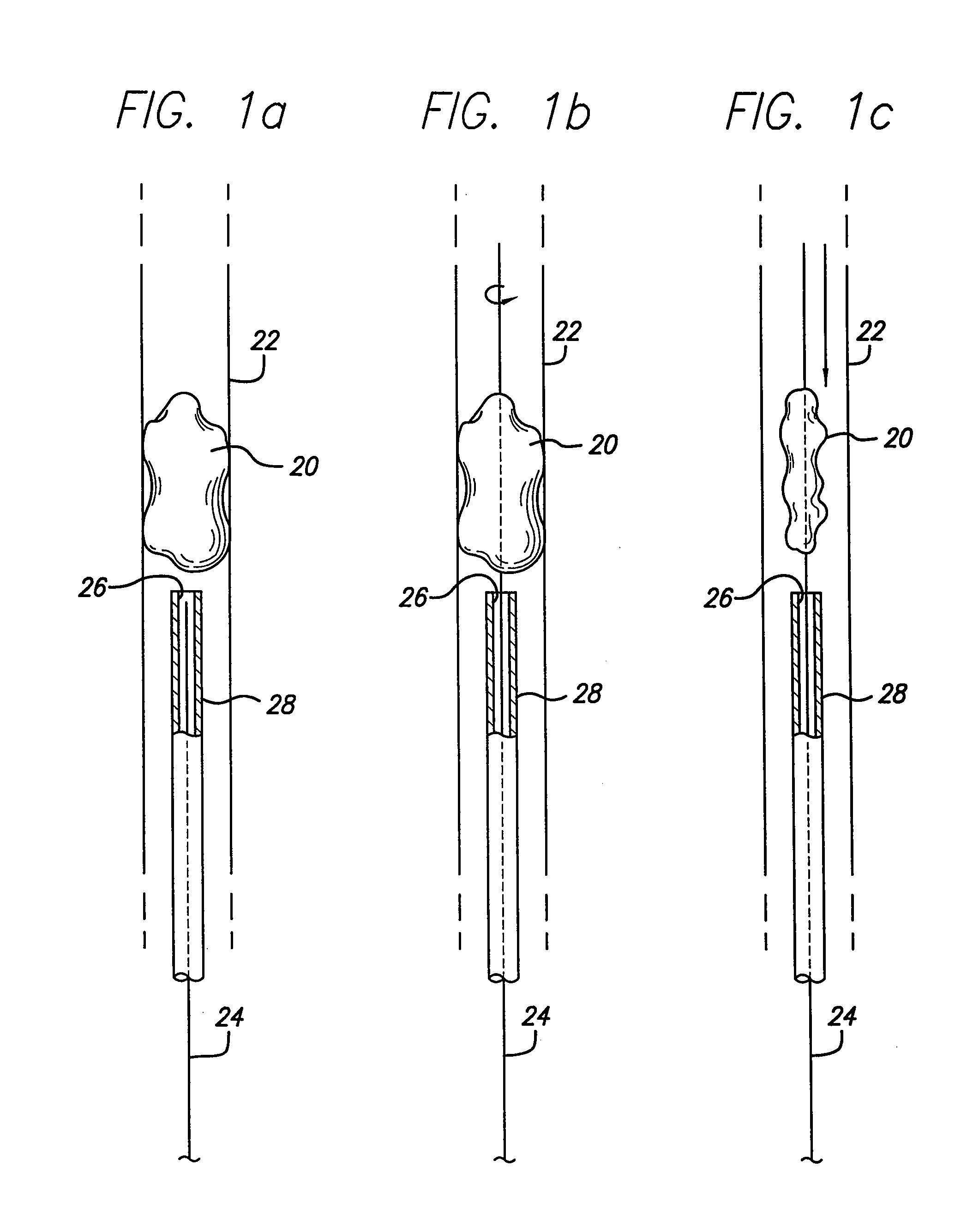
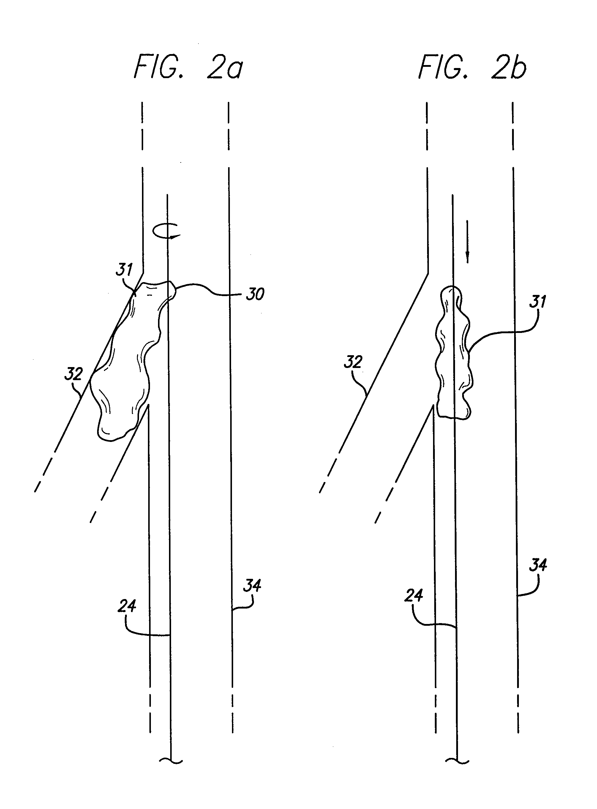
[0014]The present invention is directed to devices that are useful in removing clots and foreign bodies from vessels. Various embodiments and method of use are disclo

Problems solved by technology

These disorders are a major cause of morbidity and mortality in the United States.
When an artery is occluded by a clot, tissue ischemia (lack of oxygen and nutrients) develops.
Failure to reestablish blood-flow can lead to the loss of limb, angina pectoris, myocardial infarction, stroke or even death.
Occlusion of the venous circulation by thrombi leads to blood stasis which can cause numerous problems.
Additionally, the use of a Fogarty catheter may be problematic due to the possible risk of damaging the interior lining of the vessel as the catheter is being withdrawn.
Balloon angioplasty is appropriate for treating vessel stenosis but is generally not effective for treating acute thromboembolisms.
Unfortunately, thrombolysis typically takes hours to days to be successful.
Additionally, thrombolytic agents can cause hemorrhage and in many patients the agents cannot be used at all.
Another problematic area is the removal of foreign bodies.
The use of such removal devices can be difficult and sometimes unsuccessful.
However, such devices have been found to have structures which are either highly complex or lacking in sufficient retaining structure.
Disadvantages associated with the devices having highly complex structure include difficulty in manufacturability as well as use in conjunction with microcatheter.
Other less complex devices tend to pull through clots due to in part to the lack of experience in using the same or are otherwise inadequate in capturing clots or foreign bodies.
Moreover, systems heretofore disclosed in the art are generally limited by size compatibility and the increase in vessel size as the emboli is drawn out in the distal vascular occlusion location to a more proximal location near the heart.
If the embolectomy device is too large for the vessel it will not deploy correctly to capture the clot or foreign body and if too small in diameter, it cannot capture clots or foreign bodies across the entire cross section of the blood vessel.
Additionally, if the embolectomy device is too small in retaining volume, as the device is retracted, the excess material being removed can spill out and be carried by flow back to occlude another distal vessel.

Method used


Image

  • Filter/emboli extractor for use in variable sized blood vessels
  • Filter/emboli extractor for use in variable sized blood vessels
  • Filter/emboli extractor for use in variable sized blood vessels

Examples


second embodiment

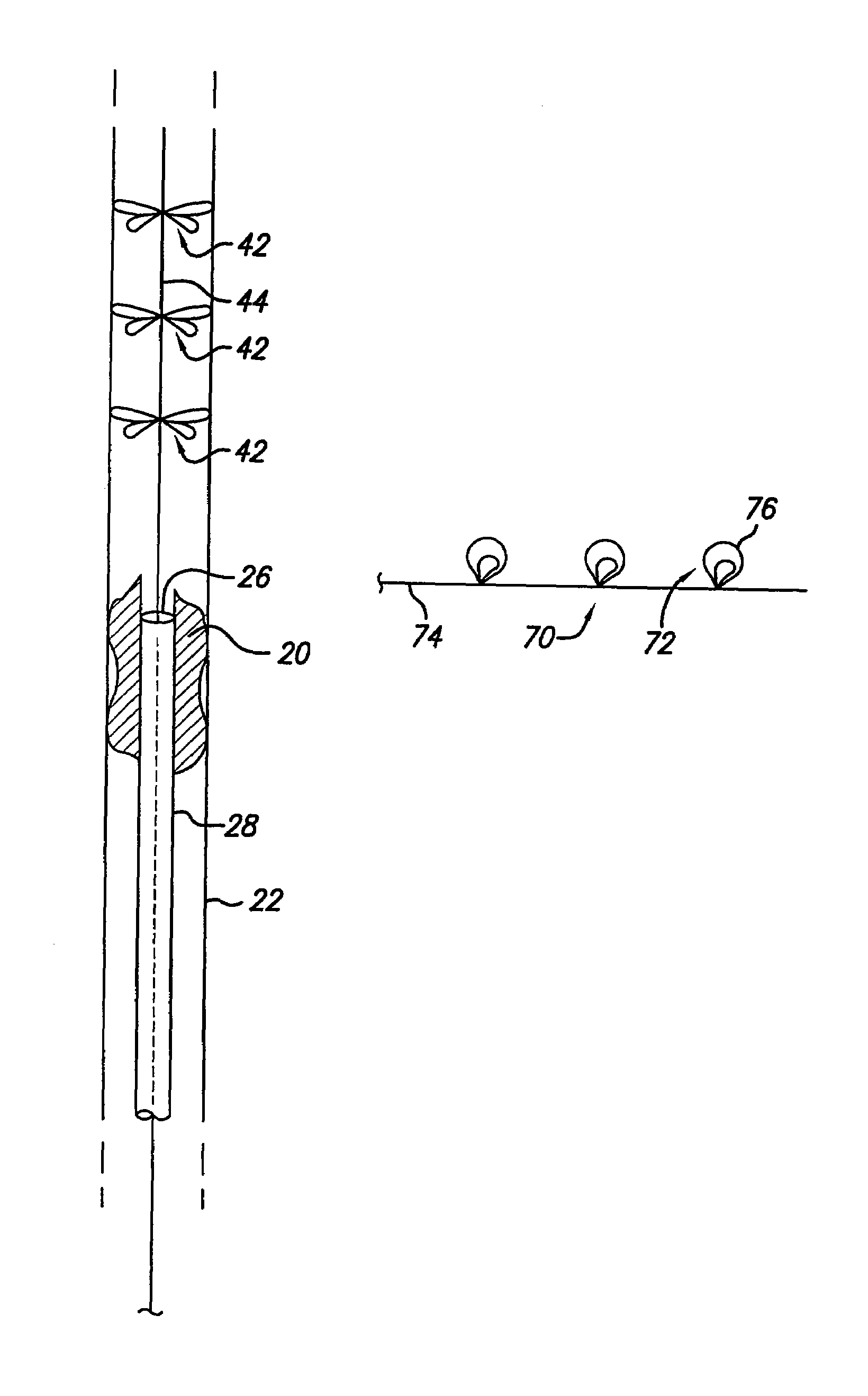
[0049]A second preferred embodiment of the present invention is shown in FIGS. 3a–d. The second embodiment is a staged filter / emboli extractor 40 that includes a plurality of spaced-apart radially extending structures 42 configured on a mandrel 44. The radially extending structure 42 each embody a plurality of loops or petals 46 arranged in an angular radial array about the circumference of the mandrel 44. As shown in the break-out illustration included in FIG. 3a which depicts an end view of one radially extending structure 42, it is contemplated that each loop or petal 46 be configured to overlay at least a portion of the next adjacent petal in an over-under pattern such that each loop / petal 46 supports another loop / petal 46. It is also contemplated that each loop / petal can overlay / underlay two or more petals in a supporting fashion.

[0050]The number of petals or loops 46 of a radially extending structure 42 can range from 3–8 or more depending on the size of the petal or loop. The...

fourth embodiment

[0067]As shown in FIG. 7, the present invention embodies a knitted or mesh, hollow basket-like extractor 80 which includes a basket 82 attached to a mandrel 84. The mandrel 84 can be a solid or tubular structure. The basket 82 includes a mesh or knitted portion 86 connected by conventional means such as welding via a plurality of proximally extending arms 88 to the distal end of the mandrel 84. The knitted or mesh portion 86 may form a cone-like configuration with its most distal end 89 defining the apex of the cone. It is to be recognized, however, that other basket configurations may also be employed. The basket-like extractor 80 is characterized by providing structure which may be particularly useful in collecting matter in its hollow interior as blood flows therethrough.

fifth embodiment

[0068]As shown in FIG. 8, a fifth embodiment in the present invention includes a hollow knitted or mesh extractor 90 attached to a distal end of a solid or tubular mandrel 92. In this embodiment, the knitted or mesh portion has a cone-like proximal portion 94 that is welded or otherwise affixed to the distal end of the mandrel 92 as well as a generally cylindrical distal portion 96 which extends integrally from the proximal portion 94. The distal most end 98 of the knitted or mesh structure terminates at a generally right angle to a longitudinal axis of the knitted or mesh portion and further defines an opening to the hollow interior of the device. This device may provide a relatively larger cross-section for blood to flow through its distal end while the device continues to trap undesirable material in a blood vessel or compress the same against the vessel wall.


PUM


Abstract

An extraction device for the removal of clots and foreign bodies from vasculature. The extractor device is connected to an elongate mandrel and is located within a longitudinally extending lumen defined by a catheter. A clot or foreign material extracted from a vessel by moving the extraction device and catheter proximally until the clot or foreign material does not perfuse a critical organ.

Description

RELATED APPLICATIONS[0001]This application is a divisional of U.S. application Ser. No. 09 / 599,146, filed Jun. 21, 2000 now U.S. Pat. No. 6,458,139 and is based upon provisional application Ser. No. 60 / 140,131 filed Jun. 21, 1999, entitled “FILTER / EMBOLI EXTRACTOR FOR USE IN VARIABLE SIZED BLOOD VESSELS.”BACKGROUND OF THE INVENTION[0002]The present invention relates to medical devices that are useful in treating thromboembolic disorders and for removal of foreign bodies in the vascular system.[0003]Thromboembolic disorders, such as stroke, pulmonary embolism, peripheral thrombosis, atherosclerosis, and the like, affect many people. These disorders are a major cause of morbidity and mortality in the United States.[0004]Thromboembolic events are characterized by an occlusion of a blood vessel. The occlusion is caused by a clot which is viscoelastic (jelly like) and is comprised of platelets, fibrinogen and other clotting proteins.[0005]When an artery is occluded by a clot, tissue isch...

Claims


Application Information

Patent Timeline
IPC IPC(8): A61M29/00A61B17/22
CPCA61B17/221A61B17/22A61B2017/2212A61B2017/22034A61B2017/22038A61B2017/00526
Inventor PALMER, OLIN J.HANCOCK, LEGAL REPRESENTATIVE, KATHERINEVOSS, LARRYKEN, CHRISTOPHER G. M.HANCOCK, DECEASED, DAVID
Owner ENDOVASCULAR TECH
Learn More