Vehicle cooler

a technology for coolers and vehicles, applied in the field of vehicle coolers, can solve the problems of increased fuel consumption, substantial energy consumption, and considerable noise, and achieve the effects of low energy consumption, low weight and volume, and high cooling capacity

Active Publication Date: 2007-02-27
OXYCOM BEHEER BV
View PDF32 Cites 30 Cited by
  • Summary
  • Abstract
  • Description
  • Claims
  • Application Information

AI Technical Summary

Benefits of technology

[0012]The present invention addresses these problems by providing a vehicle cooler having both low energy consumption and low weight and volume for a given cooling capacity. The cooler is suitable for use under most climatic conditions. In order to achieve the necessary efficiency and operating characteristics for use in cooling the interior space of a vehicle for extended periods the cooler has a high cooling capacity with little power consumption and low weight. According to a preferred embodiment, a vehicle cooler is achieved weighing less than 40 Kg and having a cooling capacity of more than 1 KW under most climatic conditions for an energy consumption of less than 250 W. This and other advantages may be achieved by use of an indirect evaporative heat exchanger which converts a flow of ambient air into a flow of cooled air having a temperature below a wet bulb temperature of the ambient air. A preferred form of evaporative heat exchanger is the dewpoint cooler, which may reduce the temperature of the air below the wet bulb temperature and to close to the dewpoint of the ambient air. Of particular significance, these advantages are achieved without requiring either a compressor or a refrigerant, making the cooler extremely quiet and environmentally friendly.
[0015]Advantageously, the first and second surfaces of the vehicle cooler may comprise opposite surfaces of a heat exchange membrane. The primary and secondary air may then preferably flow in counter flow over these opposing surfaces. Such an arrangement is considered advantageous in terms of efficiency of operation.
[0017]In a particularly advantageous embodiment the heat transfer elements may comprise elements or protrusions attached to or formed on the heat exchange membrane. These heat transfer elements serve to increase an effective surface area of the membrane. The elements may be formed as fins and may be generally aligned with a direction of air flow or may be used to cause alignment of the flow. Such elements have been found extremely advantageous in increasing heat conduction between membrane and flow. While not wishing to be bound by theory it is believed that this may be due to various mechanisms including increased surface area and improved break-up of the various boundary layers in the flow. The elements may also be provided with further break-up means such as surface roughness or louvers or the like.
[0018]In a particularly advantageous embodiment, at least the second surface may comprise a liquid retaining layer for retaining a liquid to be evaporated. The presence of an appropriate liquid retaining layer is an important factor in ensuring effective evaporative cooling below the wet bulb temperature.
[0019]Most preferably, the secondary air is cooled to a temperature below the first temperature prior to humidifying at the second surface. By this mechanism, it has been found that a greater quantity of thermal energy can be transferred from the primary air to the secondary air resulting in more effective cooling of the primary air to below its wet bulb temperature.

Problems solved by technology

Known air conditioning devices of this type require substantial energy to drive the compressor and additionally often make considerable noise.
For users of vehicles with such air conditioning systems, this may manifest itself in the form of increased fuel consumption.
Additionally, such air conditioning systems may require more power than a battery supply can provide for more than a short period.
For trucks and buses running on idle while the driver rests, the noise, fumes and energy consumption are all a significant problem.
Such generators may be located at a distance from the vehicle but also causes additional noise to that already produced by the air conditioning compressor.
They also lead to additional energy consumption and are not suitable for being left on for long periods.
Evaporative coolers have however been found relatively inefficient in lowering the temperature of the ambient air to acceptable values.
Evaporation of the water is often not optimized and only a part of the available energy that could be used for cooling is actually used.
As a result, water consumption is high.
Such devices have also been found impractical for use on most vehicles due to their relatively bulkiness for a given cooling capacity.
Furthermore, the amount of fuel available for evaporation is limited and the system is not effective once the engine has stopped.
The requirement of such desiccant or additional heating means makes the device unsuitable for continued operation on a low power supply such as is available from a normal vehicle battery.

Method used


Image

  • Vehicle cooler
  • Vehicle cooler
  • Vehicle cooler

Examples


Embodiment Construction

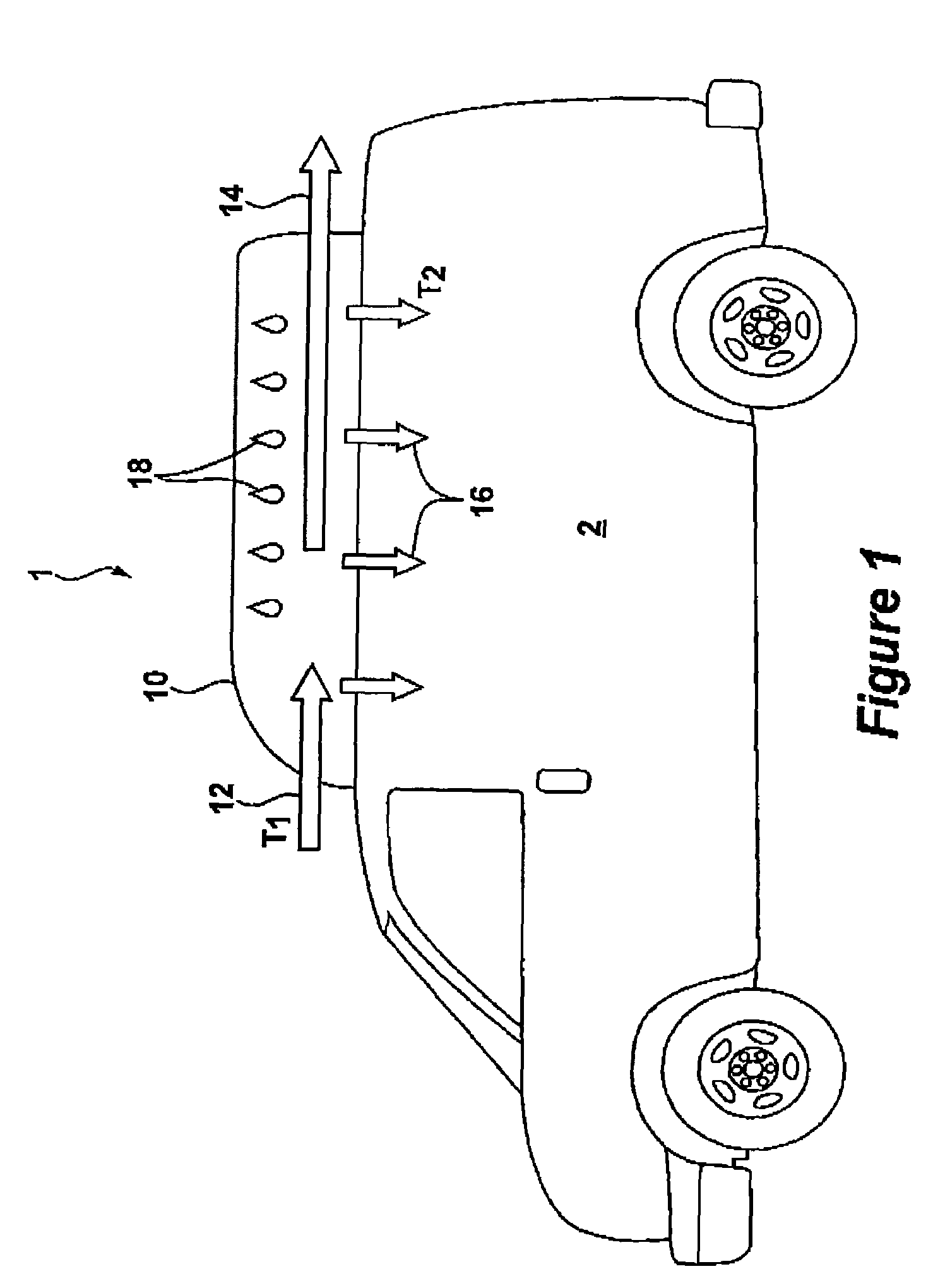
[0028]Referring to FIG. 1, there is shown a vehicle 1 provided with a vehicle cooler 10 according to the present invention. The vehicle has an interior space 2 in which the occupants of the vehicle are located. According to the present invention, the vehicle may be an automobile, truck or recreational vehicle. The invention is particularly advantageous for those situations where it is desirable to sleep or otherwise dwell within the vehicle. Under such conditions, it may be desirable to maintain the cooler operational for extended periods of time without leaving the motor running and without the requirement of an additional generator.

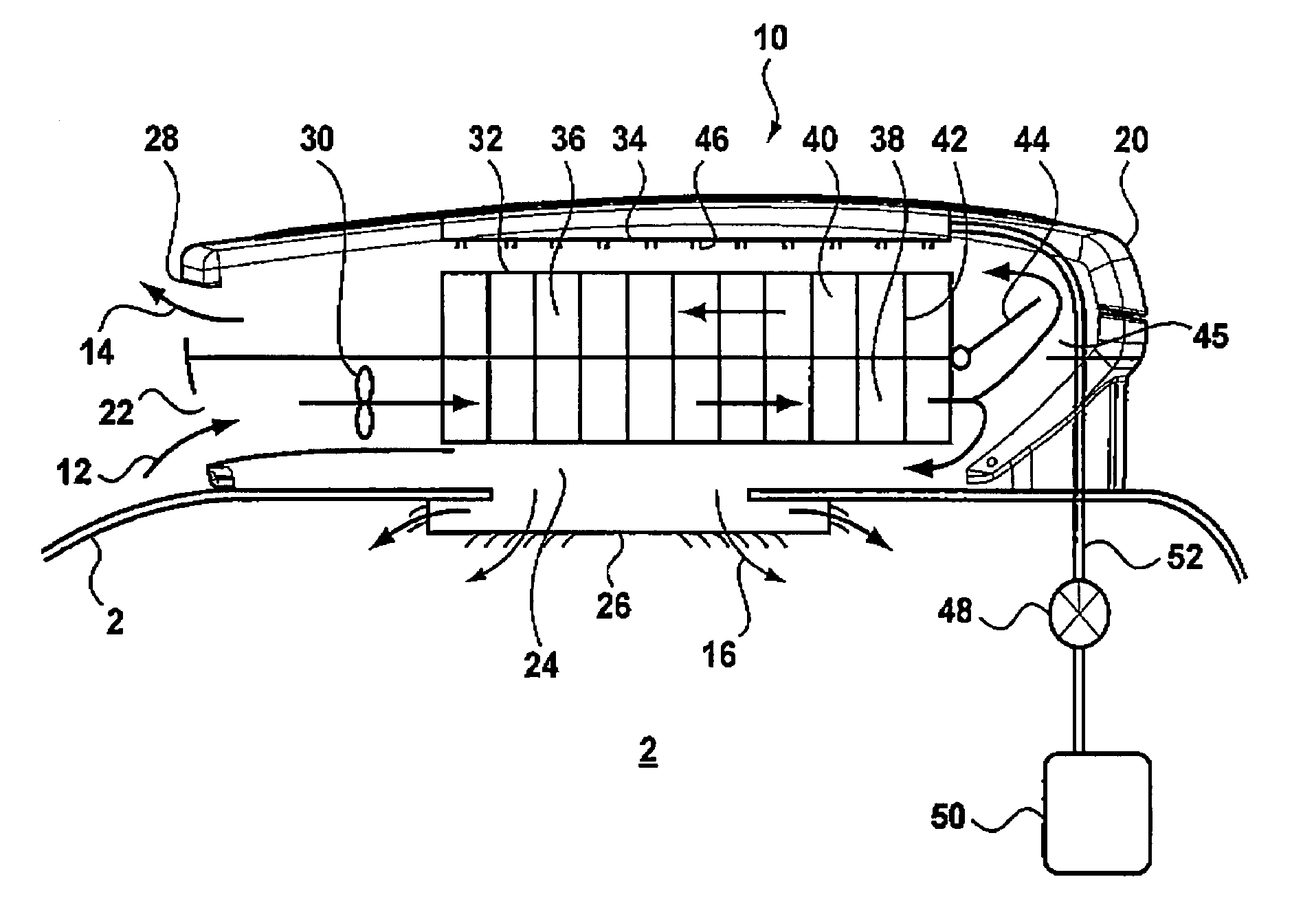
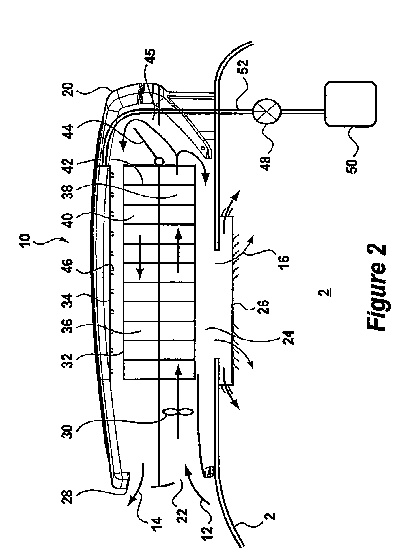
[0029]According to the schematic view of FIG. 1, the cooler 10 receives a flow of primary air 12 at a first temperature T1. The primary air 12 is cooled within the cooler 10 as will be described below by heat transfer to a flow of secondary air 14, which is exhausted to atmosphere. The cooled primary air 12 is supplied to the interior space 2 as a flow ...


PUM


Abstract

A vehicle cooler is described for providing low energy cooling to the interior of a vehicle without the use of refrigerant or a compressor. The cooler uses the evaporation of liquid from a secondary surface of a heat exchange element to cool air passing over a primary surface of the heat exchanger. The primary air is distributed to the interior of the vehicle via an air distribution mechanism, which may be adjusted from within the vehicle. The device is particularly useful for recreational vehicles.

Description

BACKGROUND OF THE INVENTION[0001]1. Field of the Invention[0002]The invention relates generally to vehicle coolers and more particularly to a device for cooling the interior passenger space of a vehicle such as truck or recreational vehicle.[0003]2. Description of the Related Art[0004]It is customary for vehicle manufacturers to include air conditioning systems in their vehicles to provide cooling air to the vehicle interior. Such systems are now standard on many models and generally work in a similar way to domestic air conditioners. The air to be cooled is passed over a heat exchange element. Within the heat exchange element, a refrigerant absorbs heat from the air and transports it away. The refrigerant is driven around a closed circuit by a compressor. Known air conditioning devices of this type require substantial energy to drive the compressor and additionally often make considerable noise.[0005]Energy consumption is increasingly of significance to consumers. For users of vehi...

Claims


Application Information

Patent Timeline
Patent Type & Authority Patents(United States)
IPC IPC(8): F28C1/00B60H1/00B60H1/32F24F1/0059F25B27/00F28D5/00F28D5/02F28F3/02
CPCB60H1/00364B60H1/245B60H1/3202B60H1/3229F28D5/02F28F3/025Y02B30/545F24F2001/0092B60H2001/00235F24F1/0007F24F1/0059Y02B30/54
Inventor REINDERS, JOHANNES ANTONIUS MARIA
Owner OXYCOM BEHEER BV
Why Eureka
Try Eureka