
Torque motor having a segment design

a technology of torque motor and segment design, which is applied in the direction of dynamo-electric machines, electrical devices, magnetic circuits, etc., can solve the problems of short circuit, damage to the electrical winding of the motor, and significant impact on production costs

Inactive Publication Date: 2007-02-27
INA DRIVES & MECHATRONICS
View PDF7 Cites 13 Cited by
  • Summary
  • Abstract
  • Description
  • Claims
  • Application Information

AI Technical Summary

Benefits of technology

[0006]The objective of the present invention is thus to make available a torque motor which allows replacement of individual segments of the electrical winding without assembly-related damage of the electrical winding and without disassembly of the whole stator and which, at the same time, can be adapted to changed power requirements, even after its original manufacture, i.e., under variable conditions of use.
[0007]An important advantage of this torque motor of the invention is that the individual stator segments have significantly smaller dimensions than the stator assembled from the segments. The individual segments can be readily manufactured with the use of standard machine tools. Shipment of the motor broken down in segments also presents no problems. The stator of the torque motor can be assembled directly at its site of use by installing the stator segments in the desired place in the stator frame. Another advantage of the torque motor is that, in the case of a defect in the electrical winding, only the stator segment with the defective section of the winding must be removed. The rest of the motor remains in perfectly good condition and completely serviceable. If care is taken during the construction of installations to ensure that the stator segments remain readily accessible, defective segments can be removed without having to remove the whole motor from the installation. Furthermore, repairs of the motor can be made very quickly by merely placing a new stator segment in the position of a defective segment.
[0008]Finally, the torque motor of the invention has the advantage that similar stator segments can be used to build different motors, whose output depends on the number of stator segments used. Different numbers of segments can be used in the stator without disturbing the operability of the motor. To produce the maximum capacity, the stator frame is equipped with stator segments along its entire circumference. If smaller powers are adequate, gaps can be left between individual stator segments, naturally, giving due consideration to the required pole count for trouble-free operation of the motor.
[0010]In an advantageous embodiment of the torque motor, the annular rotor comprises a rotor frame and permanent magnets mounted on it. In this way, a permanent excitation field is provided, so that power supply to excitation windings of the rotor is unnecessary. Due to this elimination of electric sliding contacts, the torque motor requires only a small amount of maintenance.
[0011]In accordance with a modified embodiment, the electrical windings of several stator segments are electrically connected by electrical connecting elements, which run between the stator segments and are detachable. The type of electrical connection of the individual windings depends on the selected mode of operation. For example, several windings can be connected in parallel to form units, which in turn can be electrically connected in series. The connecting elements can be realized, for example, by plug connections or screw connections. This allows quick disassembly of individual stator segments.
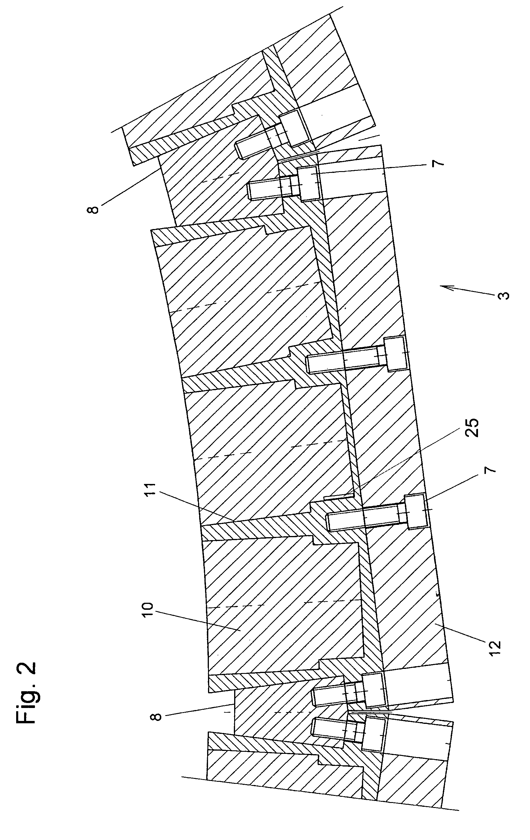
[0013]To provide a simple means of achieving circular alignment of the stator segments, it is advantageous if the frame webs have lateral faces that are angled relative to one another and thus lie on different radial planes. In this regard, it is also possible to use frame webs with different thicknesses, thereby making it possible to vary the exact position of the stator segments. This makes it possible, for example, to achieve optimum adjustment of the cogging forces that arise during motor operation.

Problems solved by technology

However, as with other electric motors, there is the problem that very large and heavy rotating parts must be manufactured, shipped and assembled, which has a significant impact on production costs.
One of the most important causes of failure is damage to the electrical winding of the motor, which can result, for example, in a short circuit between individual windings.
Due to the size of these direct drives, disassembly is expensive.
Since the direct drive is an essential component of complex installations, the installation cannot be used during the entire repair time when such a failure occurs.

Method used


Image

  • Torque motor having a segment design
  • Torque motor having a segment design
  • Torque motor having a segment design

Examples


Embodiment Construction

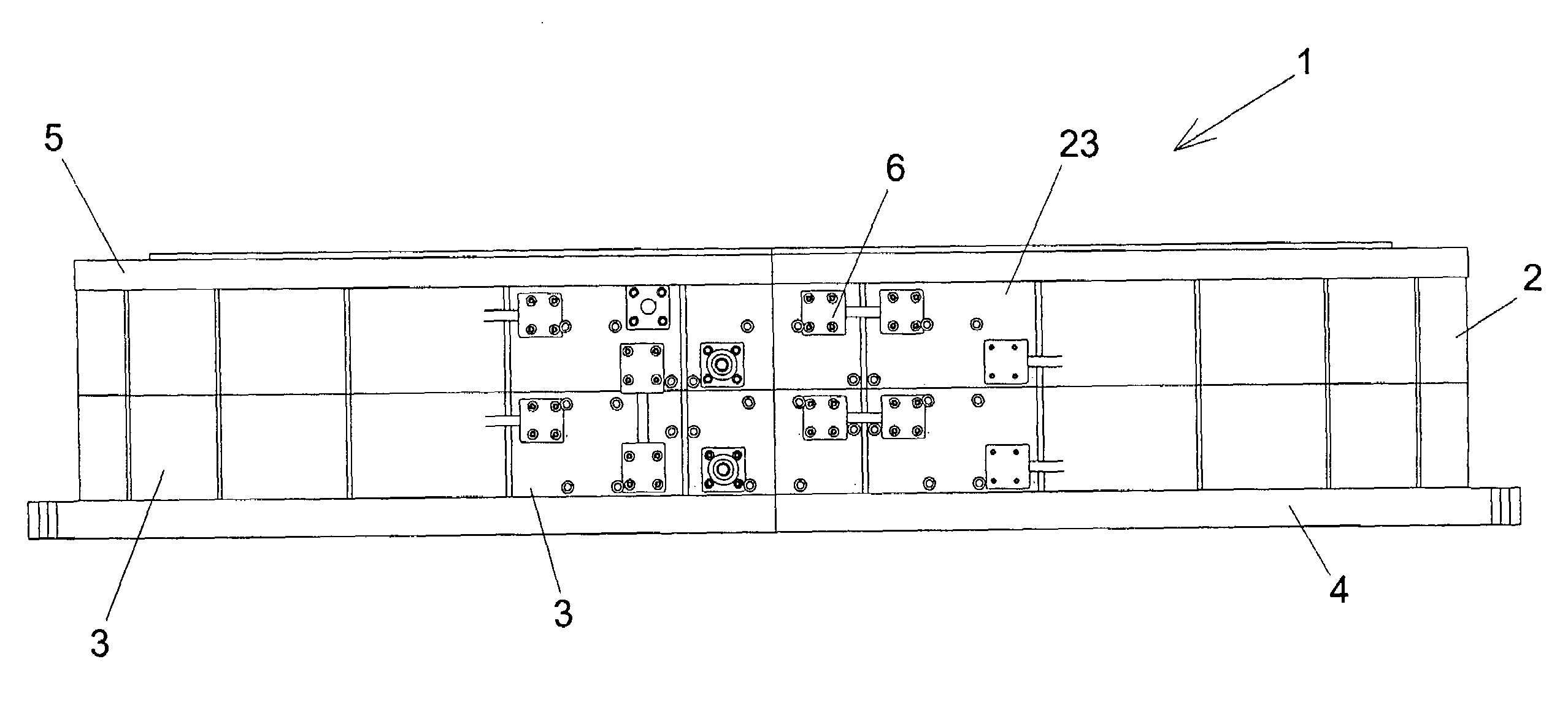
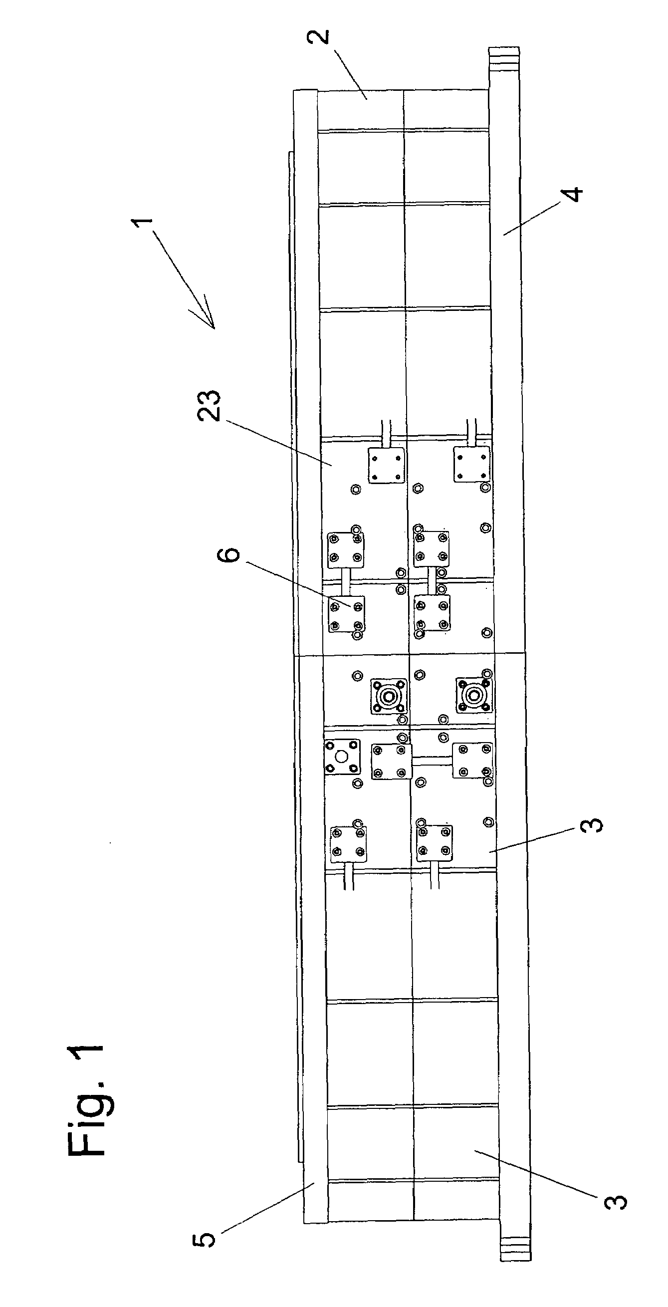
[0023]FIG. 1 shows a side view of a torque motor 1 in accordance with the invention. The illustrated embodiment is a synchronous motor with an external annular stator 2. The stator 2 consists of several stator segments 3, of which only the middle three are shown in detail in the drawing for the sake of simplicity. In the illustrated embodiment, the stator segments 3 are arranged in a row and are installed on the entire circumference of the stator. In a modified embodiment, it would be possible, for example, to leave out every other stator segment or to use even fewer stator segments than that.

[0024]A lower stator ring 4, on which the individual stator segments are set, forms the lower termination of the stator. The stator segments are covered at their upper end by an upper stator ring 5. In the embodiment illustrated in FIG. 1, the stator rings 4, 5 are used for mounting the stator segments and for increasing the stability of the stator as a whole. In other embodiments, one or both ...


PUM


Abstract

A torque motor having an annular rotor and an annular stator. The stator includes a stator frame with iron cores and electrical windings arranged thereon. The iron cores and the electrical windings are arranged in at least one independent stator segment so that each stator segment is independently operable. Each stator segment has its own housing, in which the segment's iron core and the segment's electrical winding are installed. Each stator segment is configured to occupy a predetermined angular segment ≦180° in the stator frame. Each stator segment is detachably joined to the stator frame so that the segment can be installed and removed independently of other stator segments without damaging its electrical winding or the stator frame.

Description

PRIORITY CLAIM[0001]This is a U.S. national stage of application No. PCT / EP03 / 02125, filed on Feb. 28, 2003. Priority is claimed on that application and on the following application: Country: Germany, Application No.: 102 100 71.3, Filed: Mar. 8, 2001.BACKGROUND OF THE INVENTION[0002]The present invention concerns a torque motor with an annular rotor and an annular stator, which comprises a stator frame with iron cores and electrical windings arranged thereon.[0003]Besides conventional rotary motors, which have drive functions involving the use of intermediate drive elements, so-called direct drives, in which the drive forces that are produced are delivered to the driven parts without intermediate drive elements, are being used to an increasing extent in a wide variety of technical areas. So-called torque motors of the type specified above are also counted among these direct drives.[0004]The company publication “Direct Drives & Systems” by the company ETEL S.A., Switzerland, version...

Claims


Application Information

Patent Timeline
IPC IPC(8): H02K1/12H02K1/18H02K5/20H02K9/19H02K16/00H02K26/00
CPCH02K1/12H02K1/185H02K9/22H02K2213/12H02K26/00H02K5/20H02K9/227H02K5/203
Inventor SCHMIDT, DIRKZHARSKI, VLADIMIR
Owner INA DRIVES & MECHATRONICS
Learn More