Joined bodies, luminous containers and assemblies for high pressure discharge lamps

a high-pressure discharge and assembly technology, applied in the manufacture of electric discharge tubes/lamps, cold cathode manufacturing, electrode systems, etc., can solve the problems of difference between the thermal expansion coefficient of a material, and the adhesion is susceptible to corrosion, so as to achieve the effect of significantly reducing the incidence of cracks

Inactive Publication Date: 2007-03-06
NGK INSULATORS LTD
View PDF14 Cites 9 Cited by
  • Summary
  • Abstract
  • Description
  • Claims
  • Application Information

AI Technical Summary

Benefits of technology

[0012]An object of the present invention is to provide a joined body of a first member comprising a first joining face and sapphire exposed at the first joining face and a second member comprising a second joining face and sapphire or polycrystalline alumina exposed at the second joining face, so that the joining strength can be improved and crack formation along the joining interface can be prevented.
[0019]It is considered that cracks may be induced due to the reasons (1) and (2), even when the difference of the thermal expansion coefficients is small. Further, even when the difference of the thermal expansion coefficients of sapphire and end cap is large to some degree, it is proved that crack formation in the joining portion can be prevented by lowering the joining temperature.
[0020]Specifically, when one object to be joined is sapphire and the other is sapphire or polycrystalline alumina, crack formation in the joining portion can be reduced and the joining strength can be increased by lowering the joining temperature to 1730° C. or lower. From this viewpoint, the joining temperature is preferably 1700° C. or lower.
[0021]Although the lower limit of the joining temperature is not particularly limited, the temperature is preferably 1550° C. or higher under normal circumstances, and more preferably, 1600° C. or higher. It is thus possible to prevent crack formation induced inside of the joining agent.
[0024]It is found that crack formation can be prevented by applying a joining material having the above described composition system in which the ratio of silicon is made 3 mole percent or higher and 10 mole percent or smaller calculated as silicon oxide.
[0026]According to the aspect, c-axis of the vessel of sapphire is aligned in the substantially same direction as the central axis of the discharge vessel. It is found that the incidence of cracks can thus be considerably reduced along the interface of the discharge vessel and the second member fixed at the end portion of the vessel.

Problems solved by technology

For example, when a ceramic discharge vessel for a high pressure discharge lamp and an end cap of a ceramics is joined with each other using a glass adhesive, the adhesive is susceptible to corrosion with a corrosive luminous gas filled in the discharge vessel.
Further, when they are joined using a joining material, it has been considered until now that a difference between the thermal expansion coefficient of a material for a discharge vessel and that for the end cap contributes to crack formation and a reduction of mechanical strength at the joining portion.

Method used


Image

  • Joined bodies, luminous containers and assemblies for high pressure discharge lamps
  • Joined bodies, luminous containers and assemblies for high pressure discharge lamps
  • Joined bodies, luminous containers and assemblies for high pressure discharge lamps

Examples


experiment a

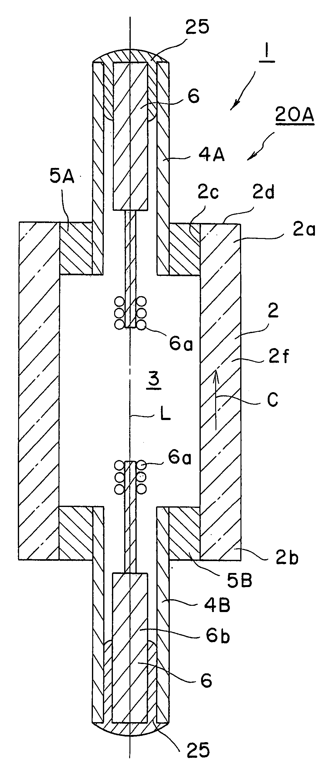
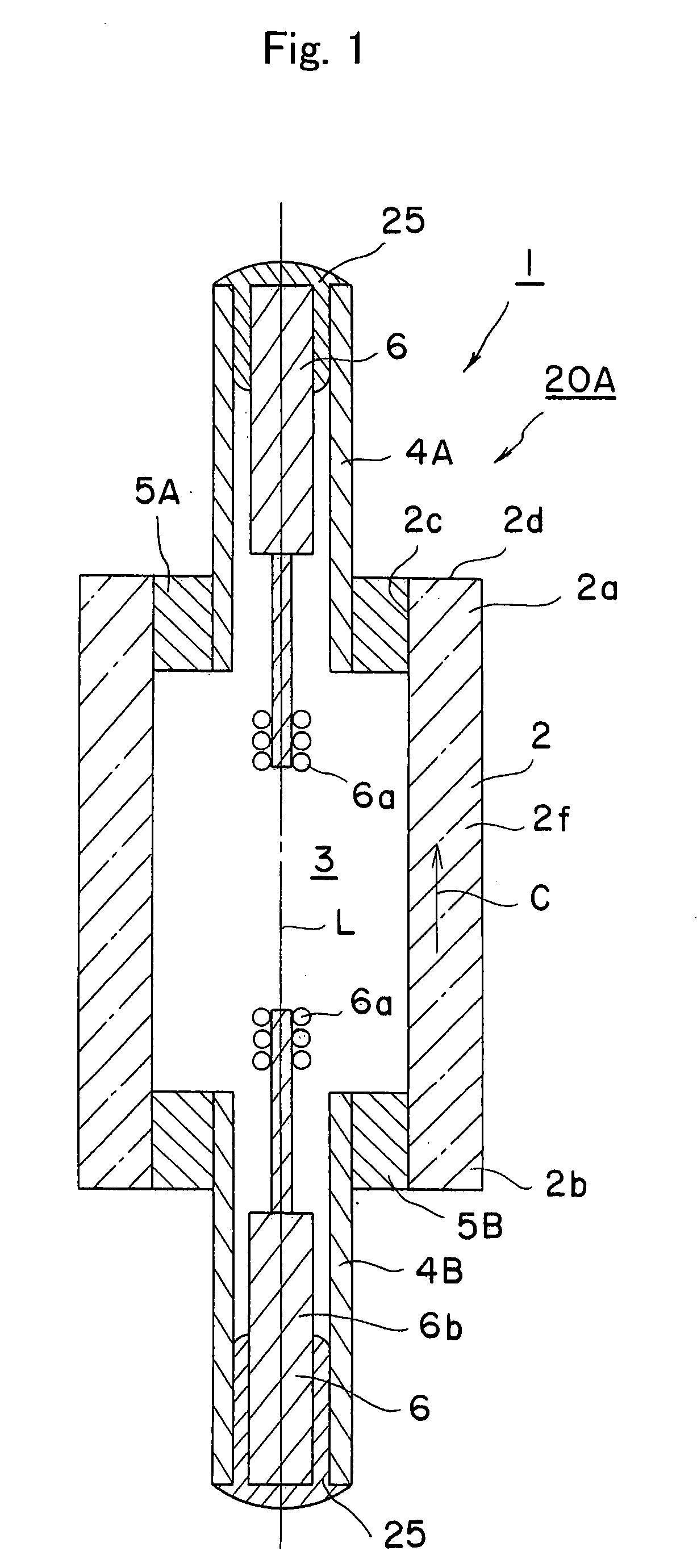
[0055]The assembly for a high pressure discharge lamp and luminous container shown in FIG. 1 were produced. Specifically, the discharge vessel 2 and sealing members 4A and 4B were formed of sapphire. The electrode member 6 was made of molybdenum.

[0056]A mixture of powdery raw materials of dysprosium oxide, alumina and silicon oxide was weighed. The ratios are shown in Table 1 (represented by an unit of molar percent).

[0057]

TABLE 1ExperimentNumberDy2O3Sc2O3Al2O3SiO21480520240852036503234650181757701310

[0058]Each mixture was shaped to obtain a ring-shaped body, which was then dewaxed at 700° C. in atmosphere. The thus obtained ring-shaped bodies were set at positions for the joining materials 5A and 5B shown in FIG. 1, and heat treated in non-oxidizing and dry atmosphere and then cooled. The temperature for the heat treatment was shown in table 2. The thus obtained luminous container of each example was stood still for 96 hours. The presence of cracks in sapphire was observed. The inc...

experiment b

[0062]The assembly for a high pressure discharge lamp and luminous container shown in FIG. 1 were produced. Specifically, the discharge vessel 2 and sealing members 4A and 4B were formed of sapphire. The electrode member 6 was made of molybdenum. The joining material was made from a mixture of powdery raw materials of dysprosium oxide, alumina and silicon oxide. The ratio was: dysprosium oxide; 65 mole percent, alumina; 32 mole percent, and silicon oxide; 3 mole percent.

[0063]The mixture was shaped to obtain a ring-shaped body, which was then dewaxed at 700° C. in atmosphere. The thus obtained ring-shaped bodies were set at positions for the joining materials 5A and 5B shown in FIG. 1, and heat treated in non-oxidizing and dry atmosphere at 1650° C. and then cooled. The angle of c-axis of sapphire and central axis “L” of the vessel was changed as shown in table 3. The thus obtained luminous container of each example was stood still for 96 hours. The presence of cracks in sapphire wa...


PUM

PropertyMeasurementUnit
angleaaaaaaaaaa
temperatureaaaaaaaaaa

Abstract

A joined body is provided, including a first member having a first joining face and sapphire exposed at the first joining face and a second member having a second joining face and sapphire or polycrystalline alumina exposed at the second joining face. The first member and second member are joined by providing a raw material for the joining material between the first and second members and heat treating the raw material at a temperature of 1730° C. or lower.

Description

[0001]This application claims the benefit of Japanese Patent Application P-2003-150512, filed on May 28, 2003, the entirety of which is incorporated by reference.BACKGROUND OF THE INVENTION[0002]1. Field of the Invention[0003]The present invention relates to a joined body, a luminous vessel and an assembly for a high pressure discharge lamp.[0004]2. Description of the Related Art[0005]A high pressure discharge lamp with a discharge vessel of quartz has been widely used as a head light for an automobile due to its high brightness and light emission efficiency. The discharge vessel has a luminous portion and contains a light emitting gas inside of the vessel. The discharge vessel of such discharge lamp is made of quartz and thus transparent, so that the luminous portion may function as a point light source.[0006]The assignee has filed a Japanese patent publication 2001-76677A, and disclosed a method of inserting pipes of molybdenum into openings at both ends, respectively, of a discha...

Claims


Application Information

Patent Timeline
Patent Type & Authority Patents(United States)
IPC IPC(8): H01J17/18H01J61/36C09K11/08C09K11/77H01J5/40H01J5/48H01J9/26H01J9/40H01J61/30
CPCC09K11/7706C09K11/7774H01J61/363H01J9/266H01J9/40H01J5/40C09K11/77064C09K11/77068C09K11/77744
Inventor NIIMI, NORIKAZU
Owner NGK INSULATORS LTD
Why Eureka
Try Eureka