Method for generating high-speed particle and system for generating high-speed particle

a high-speed particle and generating method technology, applied in the direction of instruments, nuclear engineering, nuclear targets, etc., can solve the problems of insufficient reduction of inability to obtain sufficient optical intensity, and inability to reduce the laser beam in the condensing position. achieve the effect of high positional precision

Inactive Publication Date: 2007-03-13
HAMAMATSU PHOTONICS KK
View PDF7 Cites 2 Cited by
  • Summary
  • Abstract
  • Description
  • Claims
  • Application Information

AI Technical Summary

Benefits of technology

[0007]In accordance with the aforementioned high-speed particle generating method (high-speed particle generating method according to the present invention), the wave front of the reference light generated from the predetermined condensing point to be set by the, high-speed particle generating target is measured and stored as reference wave guide information, while the wave front of the pulsed laser beam generated from the pulsed laser beam generator and passing through the above predetermined condensing point is measured, and then the wave front of the pulsed laser beam generated from the pulsed laser beam generator is compensated based on the reference wave front. In such a way, the pulsed laser beam is condensed to the micro-spot at the predetermined condensing point, and consequently irradiated to the high-speed particle generating target to be set at the predetermined condensing point, which enables to generate high-speed particles from the high-speed particle generating target efficiently.
[0012]In addition, in the high-speed particle generating apparatus according to the present invention, preferably, the high-speed particle generating target is formed on the surface of a membrane target member, an opening and a pinhole passing the pulsed laser beam is formed in the target member, and the wave front of the pulsed laser beam passing through the opening is measured by the wave front measuring device. In this case, since the opening and pinhole passing through the pulsed laser beam is formed by the same target member as that of the high-speed particle generating target, it becomes possible to measure the wave front of the reference light and the wave front of the pulsed laser beam, respectively, and compensate the wave front of the pulsed laser beam with high positional precision.

Problems solved by technology

Namely, in the wave front compensating method described in the above reference, the spot diameter of the laser beam in the condensing position (typically condensing at a focal point of optical systems) cannot be reduced sufficiently; consequently, a sufficient optical intensity cannot be obtained.
Therefore, there is a problem that in the conventional wave front compensating method, high-speed particles cannot be generated efficiently.

Method used


Image

  • Method for generating high-speed particle and system for generating high-speed particle
  • Method for generating high-speed particle and system for generating high-speed particle
  • Method for generating high-speed particle and system for generating high-speed particle

Examples


first embodiment

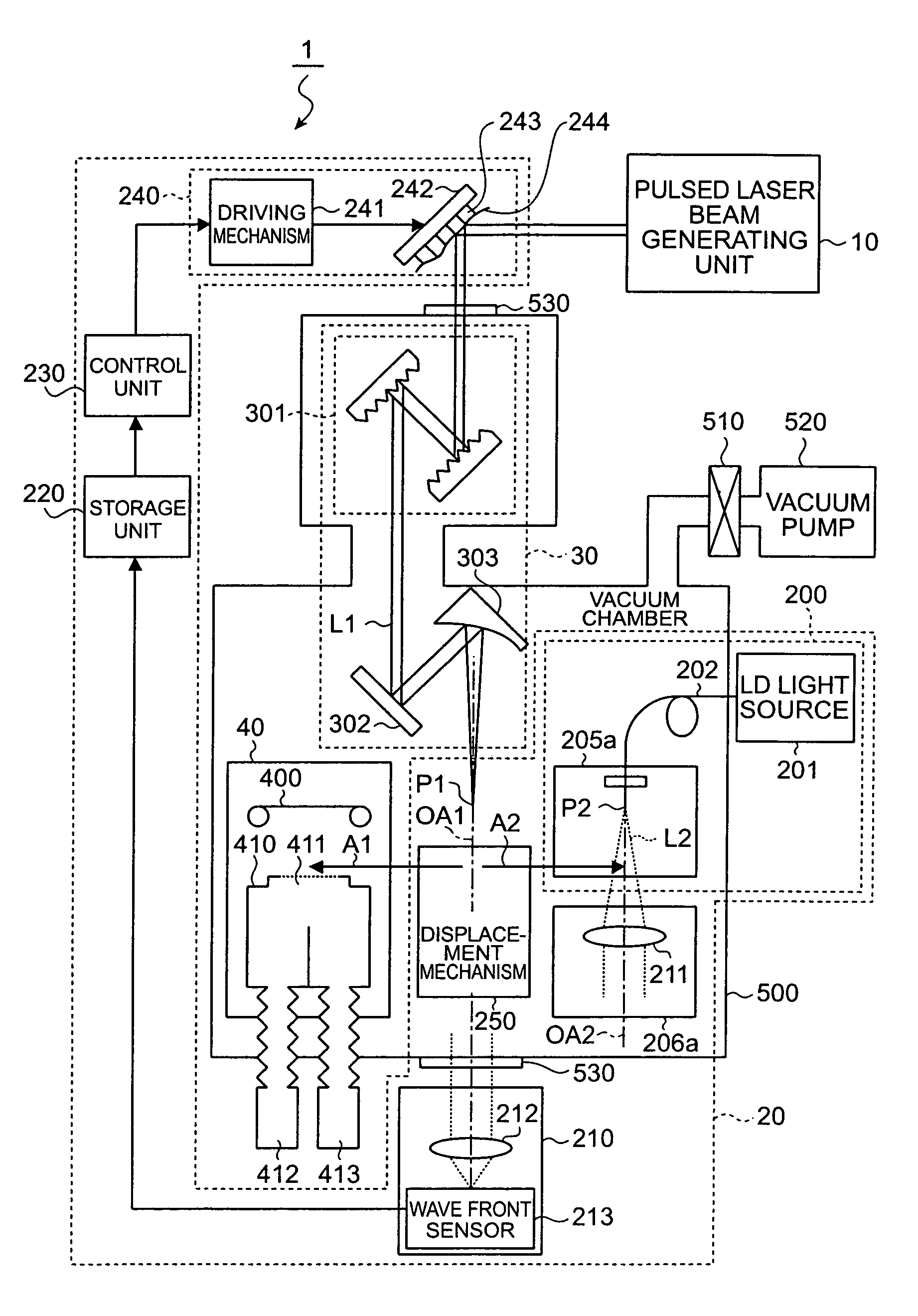
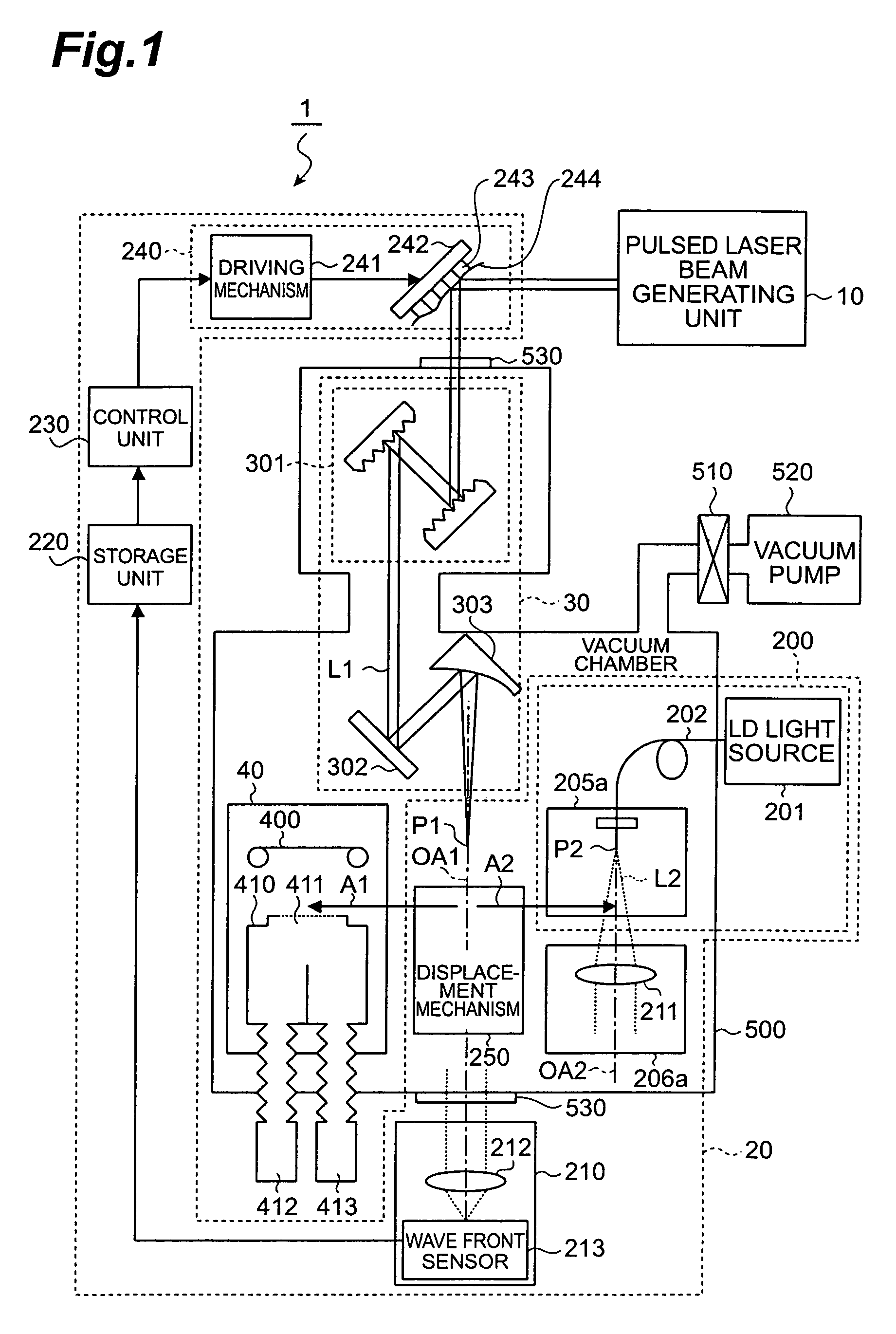
[0028]FIG. 1 is a view showing a construction of a first embodiment of a high-speed particle generating apparatus according to the present invention. As shown in FIG. 1, a high-speed particle generating apparatus 1 according to the first embodiment comprises: a pulsed laser beam generating unit 10; a wave front compensating unit 20; an irradiation optical system 30; and a target unit 40. In addition, the pulsed laser beam generating unit 10 generates a high peak-power pulsed laser beam L1. The wave front compensating unit 20 compensates the wave front of the pulsed laser beam L1. Then, the target unit 40 includes a component for generating high-speed particles by irradiation of the pulsed laser beam L1.

[0029]For example, a titanium sapphire laser for outputting the high peak-power pulsed laser beam L1 having a wavelength of 800 nm, a pulse width of 130 fs, and a maximum energy of 200 mJ, and so on is suitable for the pulsed laser beam generating unit 10. In addition, the pulsed lase...

second embodiment

[0060]A second embodiment of the high-speed particle generating apparatus according to the present invention will next be explained with reference to FIG. 7. Note that in FIG. 7 the same symbols are denoted for the components identical or equal to those of the first embodiment.

[0061]The second embodiment is different from the aforementioned first embodiment in the structures of a collimator unit 206b and a target unit 40b, and the arrangements of a wave front measuring unit 210 and a reaction unit 410.

[0062]It is a difference from the first embodiment in that the collimator unit 206b has a mirror reflector 216 in addition to a collimator lens 211, and also the target unit 40b has only a high-speed particle generating target 400 without an isotope generating unit 410. Further, a wave front detecting unit 210 is arranged in the direction (right side in the drawing) such that a reference light L2 or pulsed laser beam L1 is reflected by the mirror reflector 216 with respect to the colli...

third embodiment

[0067]A third embodiment of the high-speed particle generating apparatus according to the present invention will next be explained with reference to FIGS. 8–9.

[0068]The third embodiment is different from the aforementioned first embodiment in that a reference light generating unit (reference light generating means) 203 having a pinhole 401 and an opening 402 is applied instead of the LD light source 201.

[0069]The reference light generating unit 203 generates a reference light L2 by entering a sufficiently intensity lowered pulsed laser beam L1 in a pinhole 401. This is based on using as a reference wave front an ideal spherical wave generated by diffraction when the laser beam passes through the micro-pinhole 401.

[0070]In accordance with the high-speed particle generating apparatus 3 of the third embodiment, the reference wave front is measured by use of the reference light L2 generated by entering the sufficiently intensity lowered pulsed laser beam L1 in the pinhole 401. Secondly,...


PUM


Abstract

The present invention relates to a high-speed particle generating method and so on for generating high-speed particles from a high-speed particle generating target by condensing a pulsed laser beam to a micro-spot on the surface of a high-speed particle generating target. The high-speed particle generating method is a method that generates high-speed particles by condensing a pulsed laser beam generated from a pulsed laser beam generator through an irradiation optical system at a predetermined condensing point, and irradiating the pulsed laser beam to the high-speed particle generating target that is set at the predetermined condensing point, the method including a first step of preparing a reference data, a second step of measuring the wave front of the pulsed laser beam, and a third step of compensating the wave front of the pulsed laser beam based on the reference data.

Description

TECHNICAL FIELD[0001]The present invention relates to a high-speed particle generating method and a high-speed particle generating apparatus that generate high-speed particles from a high-speed particle generating target by irradiating a pulsed laser beam to a high-speed particle generating target.BACKGROUND ART[0002]In a high-speed particle generating apparatus for generating high-speed particles by irradiating a pulsed laser beam to a high-speed particle generating target, it is necessary to condense a laser beam to a micro-spot on the target surface in order to generate the high-speed particles efficiently. However, there are many cases that in a high-intensity laser beam, the laser beam itself to be outputted has been already distorted. In addition to the beam diameter expanding due to distortion of the wave front generated during the propagation, the wave front also may be distorted due to thermal deformation of the optical system. As a result, there are some cases that the spo...

Claims


Application Information

Patent Timeline
Patent Type & Authority Patents(United States)
IPC IPC(8): H01S3/10G21K1/00H05H1/24G21G1/12H05H6/00
CPCH05H6/00G21G1/12A61N2005/1088
Inventor TAKAHASHI, HIRONORIINOUE, TAKASHIOHSUKA, SHINJITSUCHIYA, YUTAKA
Owner HAMAMATSU PHOTONICS KK
Why Eureka
Try Eureka