
Energy storage system and method for hybrid propulsion

a technology of energy storage and hybrid propulsion, applied in the direction of gas pressure propulsion mounting, electric energy management, stopper details, etc., can solve the problems of increasing the cost of dc/dc converter, increasing the cost of power electronics hardware, and affecting the performance of hybrid propulsion systems

Active Publication Date: 2007-03-13
GENERAL ELECTRIC CO
View PDF30 Cites 78 Cited by
  • Summary
  • Abstract
  • Description
  • Claims
  • Application Information

AI Technical Summary

Benefits of technology

"The patent describes a propulsion system that uses a hybrid of electric and mechanical power for propulsion. The system has an electric motor that can generate power during dynamic braking. The system also has an energy storage unit that can supply power to the motor for propulsion and receive power from the motor during braking. A switch is used to selectively connect the energy storage unit to the motor based on certain operating parameters. The technical effect of this system is improved efficiency and flexibility in propulsion, allowing for better performance and control of the vehicle."

Problems solved by technology

However, there are a number of problems associated with existing hybrid propulsion systems.
However, the electronics required for the bi-directional DC / DC converter significantly increase the cost of the power electronics hardware.
However, the “H” bridge configuration requires at least twice the number of power electronic switches, significantly increasing cost of the DC / DC converter.
A DC / DC converter of a high power rating also presents a potential reliability issue.
Furthermore, due to the higher power requirements, the energy storage units of conventional hybrid propulsion systems require parallel operation of multiple smaller energy storage units.
However, power sharing within the parallel energy storage units may be a problem during operation over a wide range of environmental temperature extremes.
If power sharing is not adequately controlled, the life of the energy storage units may be reduced.
This results in significantly reduced fuel economy.

Method used


Image

  • Energy storage system and method for hybrid propulsion
  • Energy storage system and method for hybrid propulsion
  • Energy storage system and method for hybrid propulsion

Examples


Embodiment Construction

[0015]The present techniques provide a distributed energy storage system and method for use in hybrid propulsion systems. The techniques will be particularly advantageous in heavy duty vehicles, such as transit buses, trucks, locomotives, off-highway vehicles, etc.

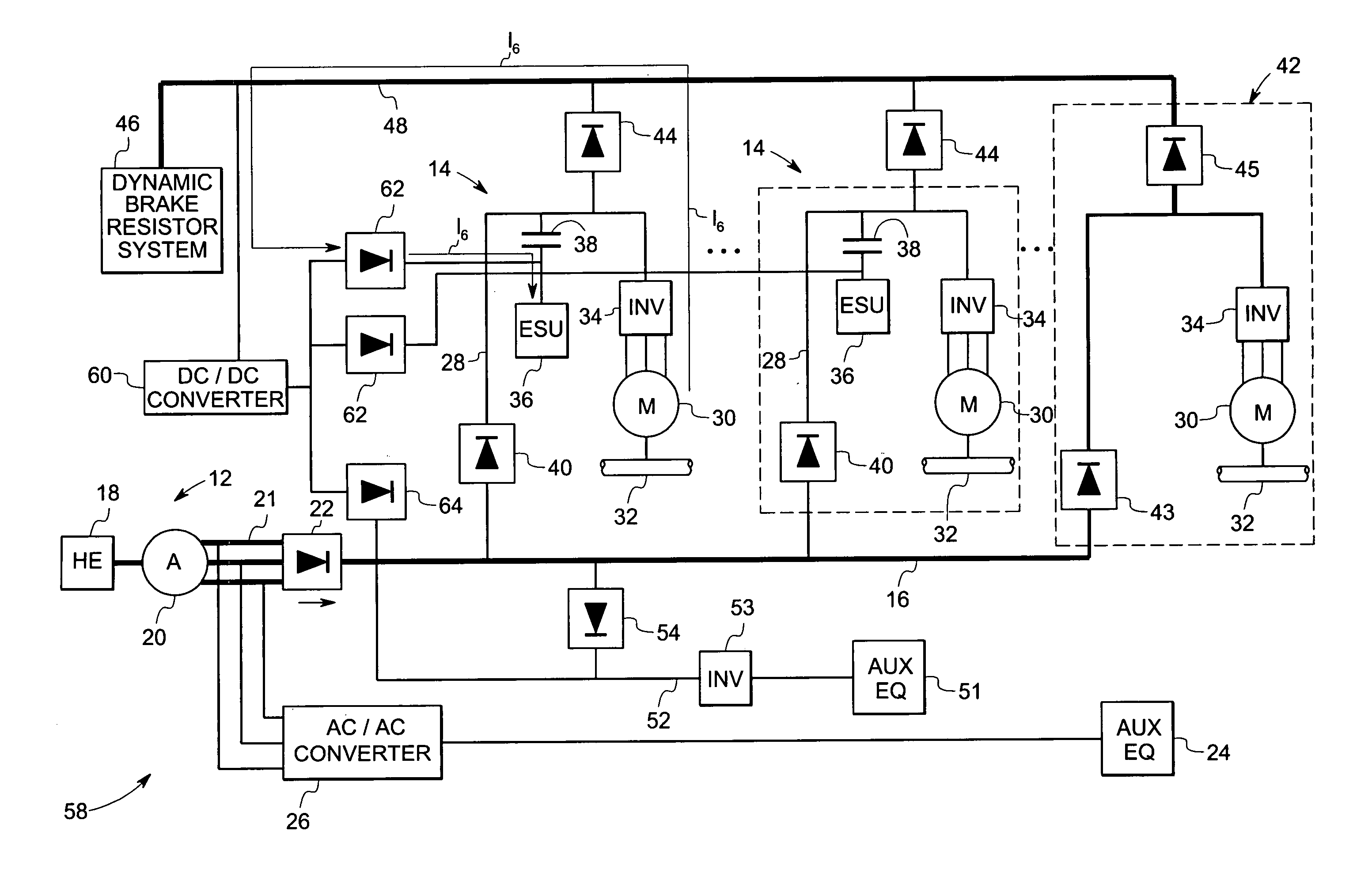
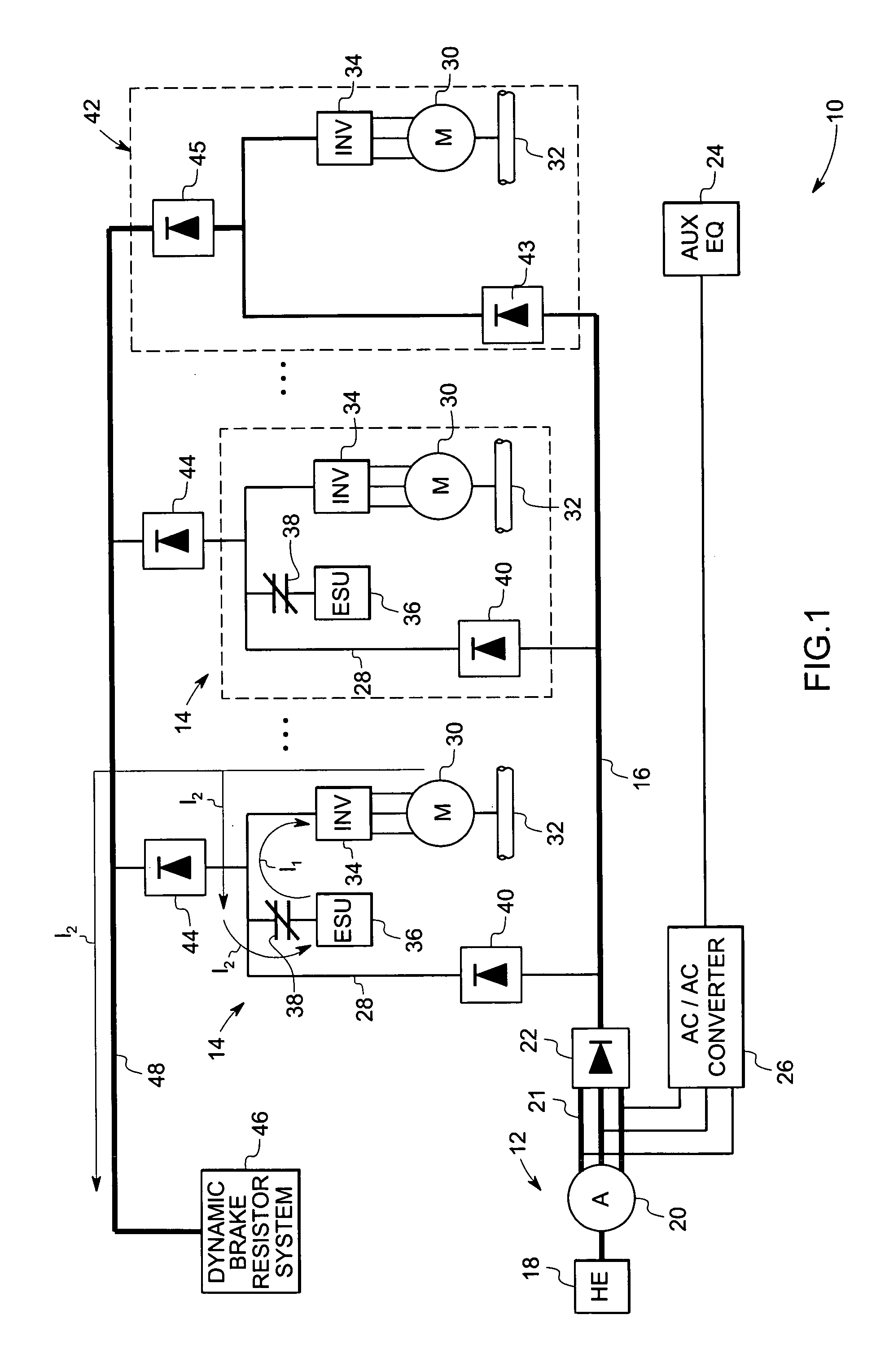
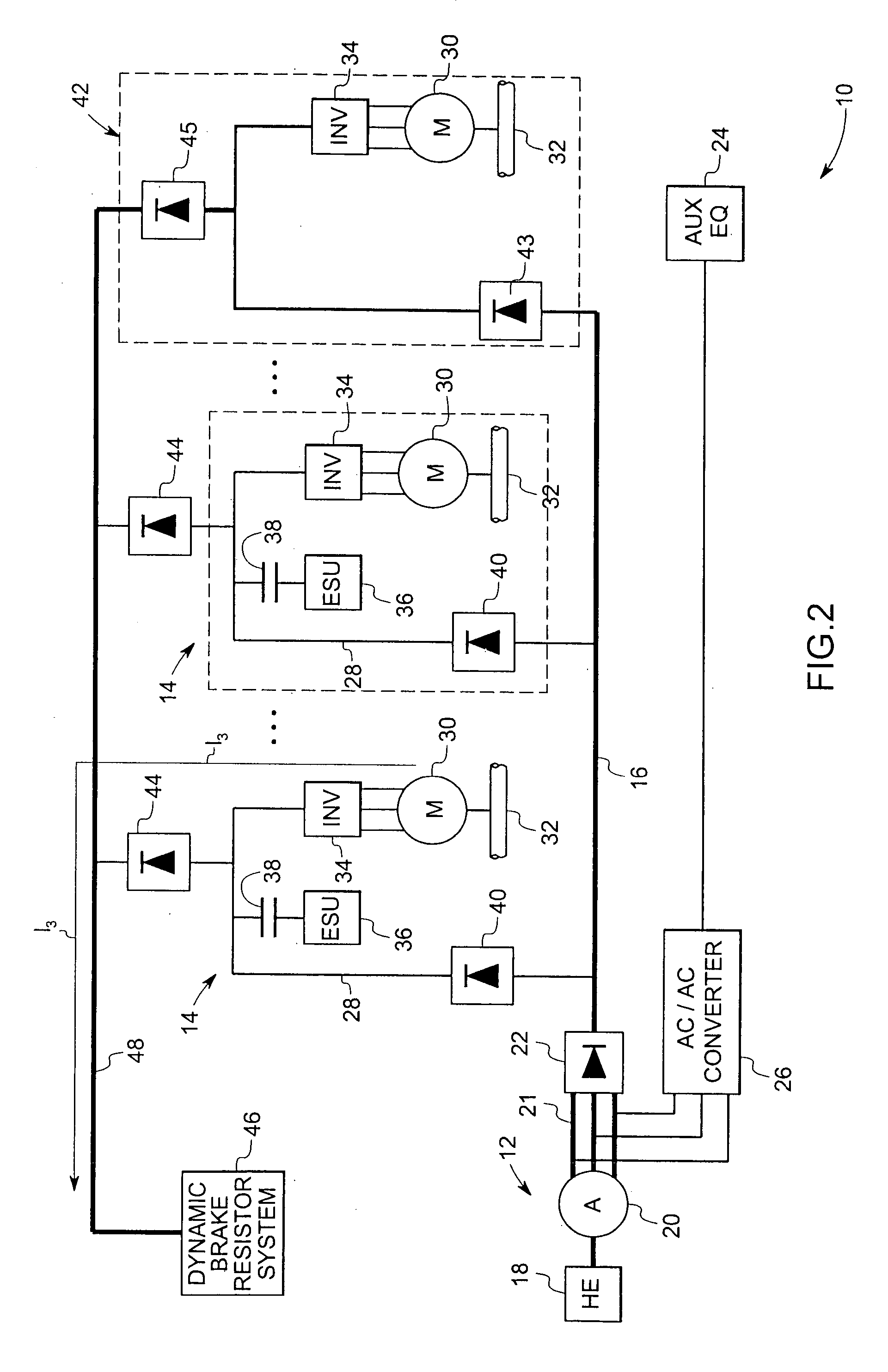
[0016]FIG. 1 and FIG. 2 illustrate a hybrid propulsion system 10 in accordance with aspects of the present techniques. The system 10 comprises an on-board power generation system 12, which is operable to supply power to at least one hybrid propulsion traction drive 14. The hybrid propulsion traction drives 14 are electrically coupled to the on-board power generation system 12 via a main direct current (DC) link 16. The term DC link is used herein to refer to positive and negative DC buses, which have portions at different voltage levels due to various components of the system 10. The illustrated on-board power generation system 12 utilizes a heat engine 18, such as a gasoline engine, a diesel engine, a gas turbine, etc. Th...


PUM


Abstract

A hybrid propulsion system. The system comprises one or more hybrid propulsion traction drives having an electric motor operable to produce mechanical power for propulsion. A hybrid propulsion traction drive is operable to receive power from an on-board power generation system. The electric motor is operable to receive power from an energy storage unit and operable to supply power to the energy storage unit. The energy storage unit may be coupled to the electric motor via a switch.

Description

BACKGROUND[0001]The invention relates generally to hybrid propulsion systems, and in particular to a system and method for distributed energy storage in heavy duty hybrid propulsion applications.[0002]Some vehicles use electric traction motors to propel the vehicle. Typically, the electric traction motors are connected to a link, such as a bus, that provides the motors with power. One or more on-board alternators may be used to provide the power to the link. In certain operating conditions, such as when the vehicle is decelerating or is maintaining speed on a downhill grade, the back-emf produced by the electric motors is greater than the voltage provided by the engine-driven alternator. Under such conditions, the electric traction motors cease acting as motors and become alternators. This process, known as dynamic braking, is a form of electric braking that is used to reduce wear on the mechanical brake system components on a vehicle. In the case where the vehicle is a locomotive, ...

Claims


Application Information

Patent Timeline
Patent Type & Authority Patents(United States)
IPC IPC(8): B61C3/00B60K6/00H02P3/14B60L11/18
CPCB60L11/18B60L2210/20B60L2200/26Y02T10/725Y02T10/7005B60L50/60Y02T10/70Y02T10/72
Inventor KING, ROBERT DEANSONG, DONGWOOSALASOO, LEMBITKUMAR, AJITH KUTTANNAIR
Owner GENERAL ELECTRIC CO
Learn More