
Automatic power controller

Inactive Publication Date: 2007-03-13
MEDIATEK INC
View PDF3 Cites 4 Cited by
  • Summary
  • Abstract
  • Description
  • Claims
  • Application Information

AI Technical Summary

Benefits of technology

[0010]In view of the above-mentioned problems, an object of the invention is to provide an automatic power controller capable of rapidly changing and stabilizing the output power of the laser light source.
[0014]By making the voltage difference between the comparison signal and the reference signal substantially the same, the voltage Vc across the capacitor C will then be kept substantially unchanged, which in turn reduces the occurrence of charging / discharging the capacitor C, therefore the time for the automatic power controller to reach its new steady state is shortened while changing the laser output power.

Problems solved by technology

However, such a design will then result in that the automatic power controller 10 needs a long time to reach the steady state which is found to frequently cause the servo control in the optical disk drive to fail.
For example, the seeking error signal may be out of control range.
For practical implementation, such a design is too complicated.

Method used


Image

  • Automatic power controller
  • Automatic power controller
  • Automatic power controller

Examples


first embodiment

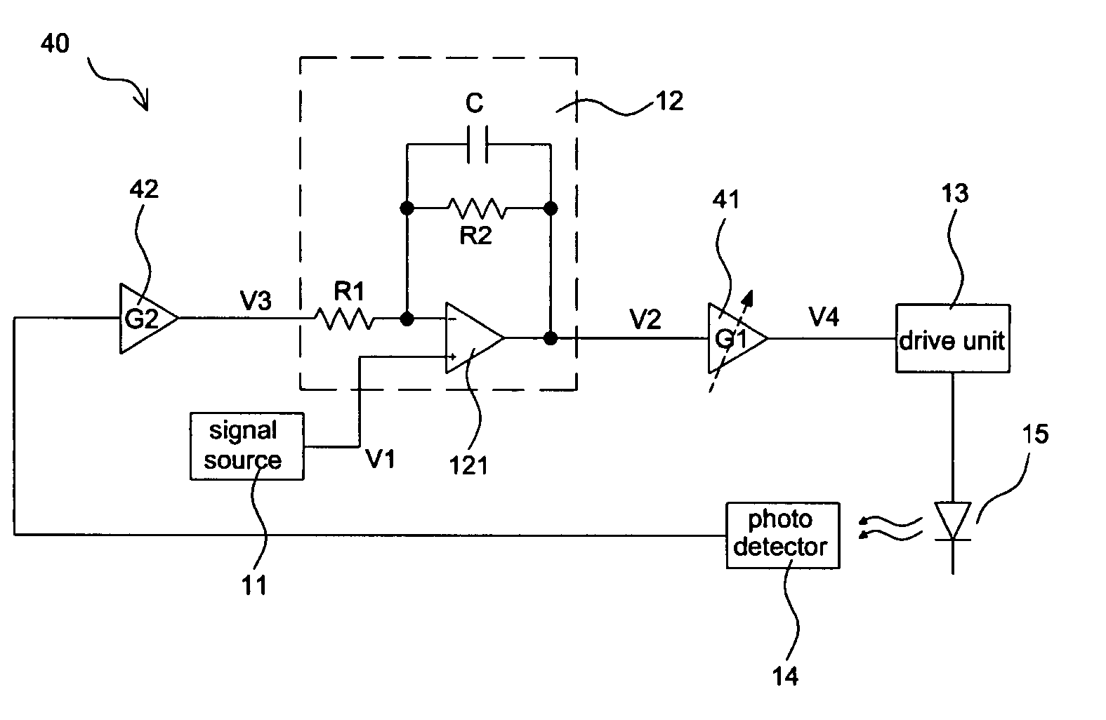
[0024]FIG. 4 illustrates an architecture diagram of an automatic power controller for a laser light source in an optical disk drive according to the present invention. Referring to FIG. 4, the automatic power controller 40 includes a signal source 11, a comparator 12, a drive unit 13, a photo detector 14, and a laser light source (for example, a laser diode) 15. The signal source 11 could be a digital-to-analog converter, or the like, for transferring a digital data (not shown in the figure) to an analog reference signal V1. The automatic power controller 40 further includes a gain-adjustable amplifier (G1) 41 disposed between the comparator 12 and the drive unit 13 and a front amplifier (G2) 42 disposed between the photo detector 14 and the comparator 12. The gain-adjustable amplifier 41 is regarded as a voltage adjusting unit. The comparator 12 includes an OP amplifier 121, resistors R1 and R2, and a capacitor C, wherein the output signal level of the OP amplifier 121 depends on t...

second embodiment

[0029]FIG. 5 illustrates an architecture diagram of an automatic power controller for a laser light source in an optical disk drive according to the present invention. Referring to FIG. 5, in addition to a first signal source 52, a comparator 12, a drive unit 13, a photo detector 14, and a laser light source 15, the automatic power controller 50 further includes an adder 51 disposed between the comparator 12 and the drive unit 13, a second signal source 53, and a front amplifier (G2) 42 disposed between the photo detector 14 and the comparator 12. The adder 51 and the second signal source 53 are regarded as a voltage adjusting unit. The comparator 12 includes an OP amplifier 121, resistors R1 and R2, and a capacitor C. Note that, as familiar with those skilled in the art, the resistor R2 in the comparator 12 may be omitted without harming the basic function of the comparator.

[0030]The difference between the automatic power controller 50 of this embodiment and the automatic power con...


PUM


Abstract

An automatic power controller includes a photo detector for detecting the output power of the laser light source and generating a detection signal, a comparator for comparing the detection signal with a reference signal and outputting a comparison signal, a signal source for providing the reference signal with different voltages representing different output power levels of the laser light source to be set, and a gain-adjustable amplifier for receiving the comparison signal and generating an output signal. The gain of the gain-adjustable amplifier is adjusted so that the voltage difference between the steady-state voltage of the comparison signal and the voltage of the reference signal is kept substantially unchanged regardless of the output power of the laser light source, the occurrence of charging / discharging the capacitor in the comparator is reduced. Therefore the automatic power controller can rapidly reach its new steady state while changing the laser output power.

Description

[0001]This Non-provisional application claims priority under 35 U.S.C. § 119(a) on patent application Ser. No(s). 092107029 filed in Taiwan on Mar. 26, 2003, the entire contents of which are hereby incorporated by reference.BACKGROUND OF THE INVENTION[0002]1. Field of the Invention[0003]The invention relates to an automatic power controller for a laser light source in an optical disk drive, and more particularly to an automatic power controller for the laser light source in an optical disk drive, which is capable of rapidly changing and stabilizing the output power of the laser light source.[0004]2. Description of the Related Art[0005]FIG. 1 illustrates an architecture diagram of a conventional automatic power controller for a laser light source in an optical disk drive. Referring to FIG. 1, the conventional automatic power controller 10 includes a signal source 11, a comparator 12, a drive unit 13, a photo detector 14, and a laser light source (for example, a laser diode) 15. The d...

Claims


Application Information

Patent Timeline
IPC IPC(8): G01B11/00G01J1/32G01J1/46
CPCG01J1/46G01J1/32
Inventor HSU, TSE-HSIANGMA, PAO-PING
Owner MEDIATEK INC
Features
  • Generate Ideas
  • Intellectual Property
  • Life Sciences
  • Materials
  • Tech Scout
  • Unparalleled Data Quality
  • Higher Quality Content
  • 60% Fewer Hallucinations
Learn More