Bladeless conical radial turbine and method

a conical radial turbine and bladeless technology, applied in the field of bladeless or boundary layer turbines, can solve the problems of slipping in capacity, affecting the efficiency of traditional pumps, and affecting the efficiency of traditional design pumps, so as to achieve smooth direct and guide fluid.

Active Publication Date: 2007-03-20
GRANDE III SALVATORE F +1
View PDF63 Cites 37 Cited by
  • Summary
  • Abstract
  • Description
  • Claims
  • Application Information

AI Technical Summary

Benefits of technology

[0072]Another objective of a possible embodiment of the present invention is to direct fluid through a pump housing and into additional stages in a manner that changes the velocity and direction of movement of the fluid as gradually as possible to thereby increase the efficiency of operation.
[0074]One advantage of one possible embodiment of the present invention is the ability to provide a relatively small diameter downhole submersible pump for use in oil wells pumping multiphase fluids which may be driven at high rotational speeds as compared to existing downhole submersible pumps.
[0075]Another advantage of one possible embodiment of the present invention is the ability to provide identical or substantially identical axial pump stages which may be stacked together axially to increase the pump head to a desired amount for a desired fluid flow capability.
[0087]The method may further comprise providing a fluid transition region between the plurality of rotors which is shaped to smoothly guide fluid from one tubular housing section to another tubular housing section and / or providing a radial bearing in the fluid transition region with one or more fluid flow paths angled in line with the spiraling flow to receive and smoothly direct the spiraling fluid flow through the transition region.

Problems solved by technology

The vanes, buckets, or the like, of traditional pumps wear and lose effectiveness due to normal friction and / or impingement with particles such as sand or other abrasives.
These tolerances may wear away quickly in abrasive fluid pumping service so that these traditional design pumps steadily lose efficiency and eventually fail.
Traditional pump manufacturers sometimes make more income from replacement components due to wear and failure from operating in a harsh pumping environment than on the sales of original pumps.
Other problems related to traditional axial, centrifugal, and mixed flow pumps include problems relating to cavitation.
The energy required to accelerate the liquid to high velocity and fill the void left by the bubbles causes a drop in capacity.
As discussed briefly above, impingement damage is produced by solids which engage the vanes of a pump and erode it.
The higher the angle of impingement between the particle and the vane, the greater the damage, with a ninety degree impingement angle being the most damaging.
Traditional pumps are sometimes operated at lower speeds to reduce impingement wear, but lower speeds result in lower fluid flow and lower horsepower.
Other problems related to more traditional pumps include vapor lock problems, and pump efficiencies being limited by affinity laws.
The flow to head ratio is often restricted by design limitations in traditional pumps.
Turbulent flow in the stage to stage transition can be problematic.
The down thrust loading developed in some applications can be excessive.
Radial and side loading thrust is often inconsistent relative to rotational speed.
Upon startup, upthrust can be detrimental to the ultimate balance of the pump.
Stated more generally, traditional pumps are highly subject to vibrations as a natural result of impact of the vanes and blades with the fluids pumped.
This vibration problem is highly exacerbated when multiphase fluids are pumped that may include solids, liquids, and gases.
Accordingly, the shaft rotation speed of traditional pumps, especially those used for pumping multiphase fluids, is limited to avoid destroying the pump due to vibrational damage.
The limited shaft rotational speeds result in lower pump output, limited horsepower, and generally less pumping capability.
Despite the many advantages of boundary layer pumps over more traditional pumps for pumping multiphase fluids, some of which are discussed above, and despite commercial usage and considerable interest in boundary layer pumps since their invention by Tesla in 1913, solutions to certain multiphase fluid pumping problems utilizing boundary layer pumps have never been found.
Despite the long felt need for the advantages of a boundary layer pump in downhole pumping applications of multiphase fluids, and despite considerable development work of boundary layer pumps over the last century since inception by Tesla, it has never been found possible to provide downhole pumps based on boundary layer principals.
Prior art bladeless or boundary layer machines simply do not provide any solution to these pumping goals.
Existing downhole pumps are subject to the disadvantages of traditional pumps discussed above.
Lacking vanes, the impeller offers very low starting torque under a loaded condition.
The above cited art does not overcome the problems and / or appreciate the advantages discussed hereinbefore.

Method used


Image

  • Bladeless conical radial turbine and method
  • Bladeless conical radial turbine and method
  • Bladeless conical radial turbine and method

Examples


Embodiment Construction

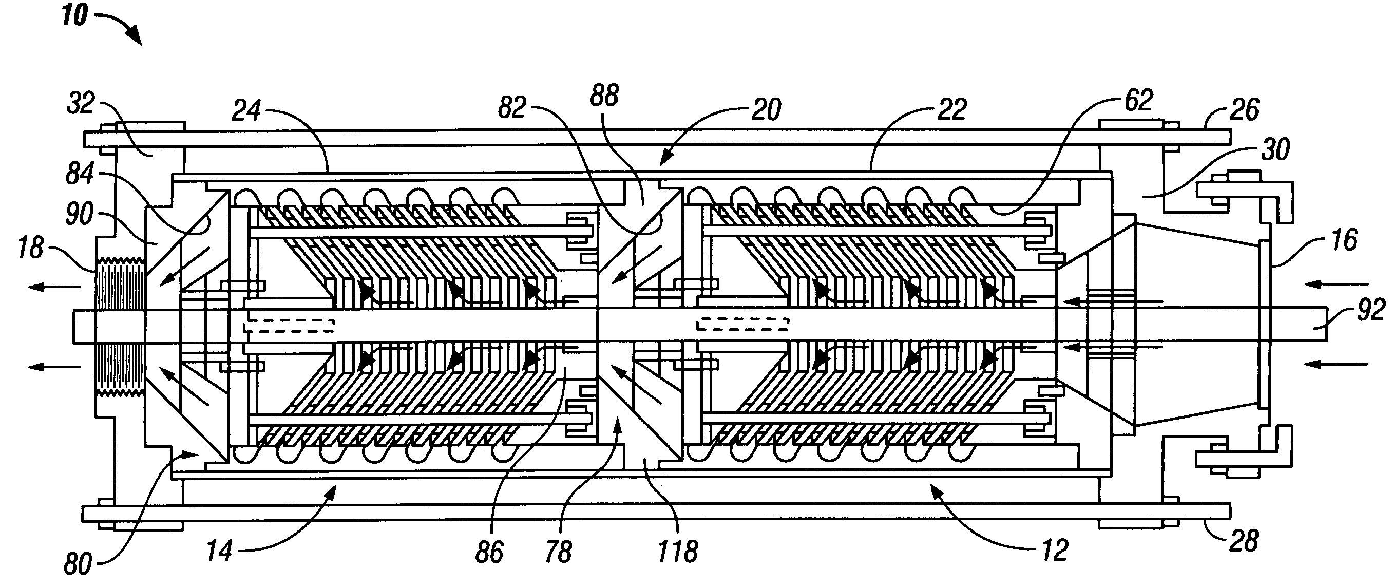
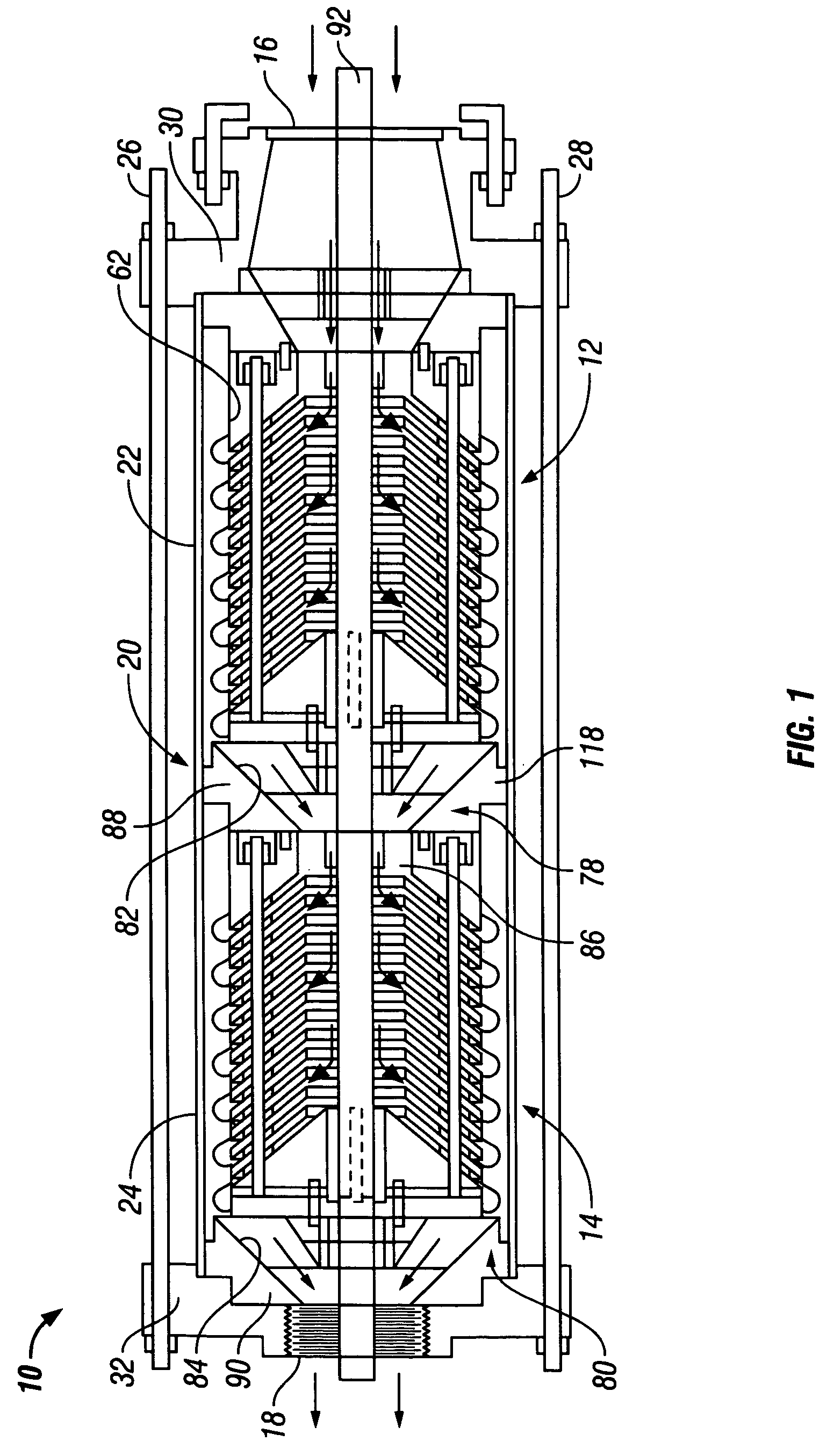
[0100]Referring now to the figures, and more particularly to FIG. 1, there is shown an embodiment of multistage boundary layer pump 10 in accord with the present invention. Pump 10 as shown comprises first boundary layer pump stage 12 and second boundary layer pump stage 14 axially interconnected together. The details and operation of multistage boundary layer pump 10 which permit the unique end-to- end interconnection of multiple boundary layer pump stages is discussed hereinafter. While only two boundary layer pump stages are shown in FIG. 1, it will be understood that many more boundary layer pump stages may be interconnected end-to-end in a similar manner as that shown in FIG. 1. Moreover, each subsequently connected boundary layer pump stage may be identical or substantially identical to the second boundary layer pump stage 14, if desired. First boundary layer pump stage 12 may utilize a different inlet 16 to mate with surrounding equipment as desired. Accordingly, for use in s...


PUM


Abstract

Turbo-machinery and methods are disclosed for a bladeless conical radial turbine wherein fluid is directed axially within the pump body to produce an axial output. The rotor comprises a plurality of spaced apart conical elements. A plurality of spiraling flow paths may be provided to receive fluid to which fluid has been imparted by acceleration of the fluid through the spaces between the conical elements using boundary layer adhesion techniques. The fluid is smoothly directed to any number of subsequent boundary layer pumping stages which are axially positioned with respect to each other.

Description

FIELD OF THE INVENTION[0001]The present invention relates generally to turbo-machinery and, more particularly, to bladeless or boundary layer turbines such as turbine pumps, engines, drivers, and the like.BACKGROUND OF THE INVENTION[0002]Boundary layer or bladeless turbines, pumps, and other related turbo-machinery have been known and patented as early as May 6, 1913 when Nikola Tesla described a boundary layer pump in U.S. Pat. No. 1,061,142. The boundary layer pump taught in that patent utilizes rotating flat disks which have no blades, vanes, or propellers, so that such pumps are now also referred to as bladeless pumps. In related U.S. Pat. No. 1,061,206, Tesla disclosed a fluid driven boundary layer or bladeless turbine which may be utilized as a prime mover, such as a hydro-electric power generator for transforming kinetic energy in flowing fluids into electrical energy. Another example of related boundary layer or bladeless turbo-machinery invented by Tesla, and described in U...

Claims


Application Information

Patent Timeline
Patent Type & Authority Patents(United States)
IPC IPC(8): F01D1/36
CPCF01D1/36F05D2250/232F05D2250/12B63H11/00
Inventor GRANDE, III, SALVATORE F.DRAPER, DAVID R.
Owner GRANDE III SALVATORE F
Why Eureka
Try Eureka