
Device and method for electrical isolation of the pulmonary veins

a technology of electrical isolation and pulmonary veins, applied in the field of paroxysmal atrial fibrillation treatment, can solve the problems of long recovery time of this invasive procedure, and achieve the effect of reducing tissue conductivity, effective electrical isolation, and not jeopardizing the patency and flow capacity of the pulmonary vein

Inactive Publication Date: 2007-03-20
MARGOLIS JAMES R
View PDF14 Cites 39 Cited by
  • Summary
  • Abstract
  • Description
  • Claims
  • Application Information

AI Technical Summary

Benefits of technology

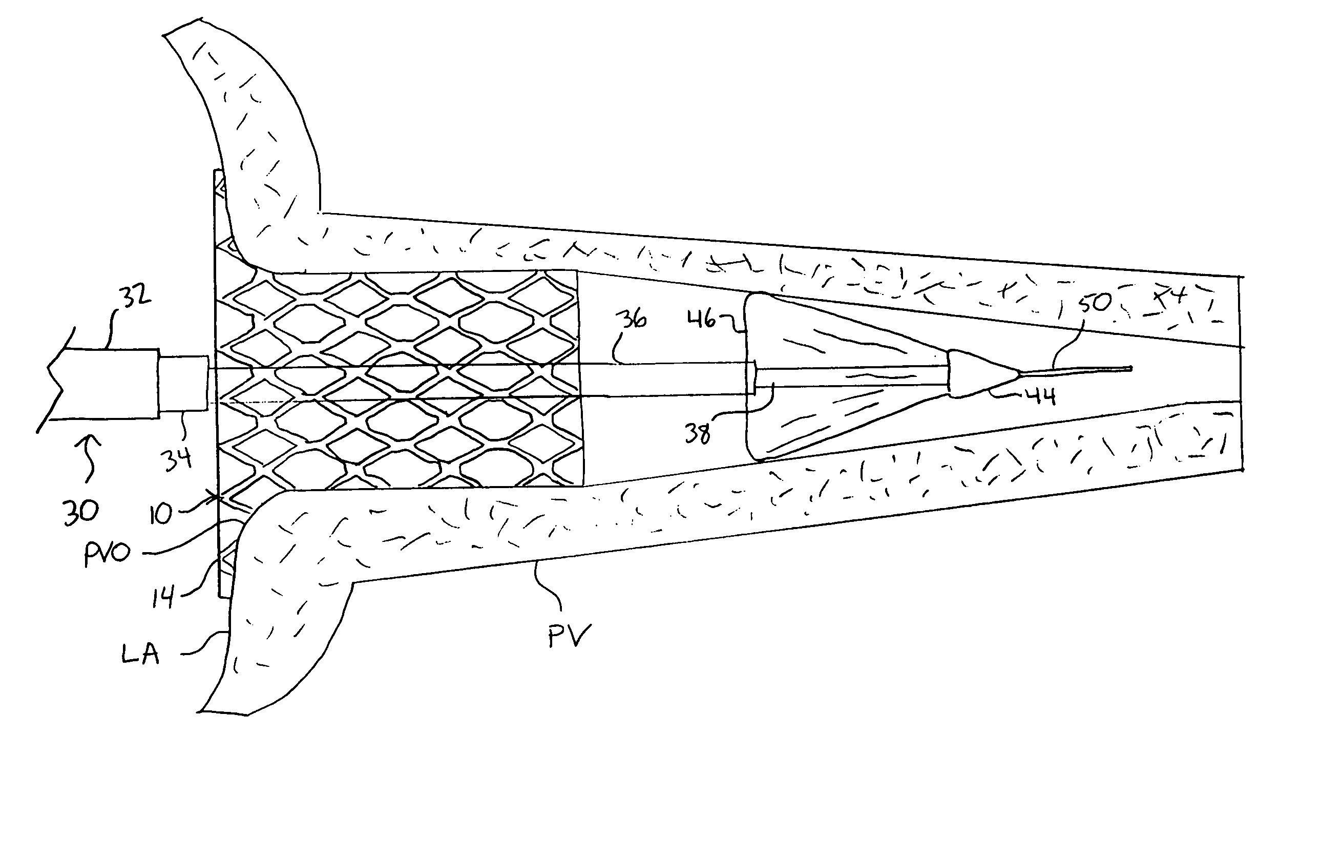
[0017]In one aspect of the present invention, the structure delivered is a self expanding stent fabricated out of a tube or flat sheet, the tube or flat sheet being made from a shape memory alloy such as Nitinolâ, Nitinol, or a cobalt / platinum based alloy. Shape memory alloys (SMA) have long been used in medical devices because of their ability to be processed and “shape set” into a desired final configuration and then manipulated into a low profile configuration that may be more easily navigated through a tortuous location in the body, such as a coronary artery or pulmonary vein. This shape setting is typically achieved by heating the SMA above a certain temperature known as the “transition temperature,” which causes any deformation introduced below the transition temperature to be reversed. Additionally, the use of stress-induced martensite alloys decreases the temperature sensitivity of the devices, making them easier to navigate and deploy. The use of these alloys as described, are discussed in detail in U.S. Pat. No. 4,485,816 (Krumme), U.S Pat. Nos. 4,665,906 and 6,306,141 (Jervis), each of which are incorporated herein by reference.
[0025]In addition, or as alternative to, making an incision and keeping it open, there is convincing data that trauma to tissue, and subsequent fibrosis or restenosis, results in significantly reduced tissue conductivity. Thus, encouraging fibrosis or restenosis, without jeopardizing the patency and flow capacity of the pulmonary vein, could result in effective electrical isolation of the left atrium from the pulmonary vein.
[0026]Numerous data exist that correlate in-stent restenosis with the percentage of stent to tissue contact. As such, currently marketed coronary stents, will typically have 20% material contact with the tissue layers of the vessel, once deployed. Increasing the percentage of stent to tissue contact may increase the likelihood that the aberrant conductive pathway creating the arrhythmia is cut when a stent is deployed, in one or more of the pulmonary veins, or it's surrounding tissues and structures.
[0027]Another aspect of the present invention provides a means for monitoring the effectiveness of the procedure. For example, a preferred embodiment provides a detachable wire fixedly attached to the distal end, and proximal end of the stent or ring structure so that the user can measure electrical continuity between the distal and proximal ends of the non-conductive structure once it has been deployed in the pulmonary vein, or it's surrounding tissues and structures. Non-conductivity may be an inherent property of the material used to create the structure. Alternatively, the inner and outer surface of the expandable structure may be treated or coated with a non-conductive coating so as to disrupt the aberrant conductive pathway, and to allow the employment of monitoring wires on either end of the structure, so as to accurately monitor current flow through the tissue rather than through the structure itself.

Problems solved by technology

Recovery time for this invasive procedure is necessarily lengthy.

Method used


Image

  • Device and method for electrical isolation of the pulmonary veins
  • Device and method for electrical isolation of the pulmonary veins
  • Device and method for electrical isolation of the pulmonary veins

Examples


Embodiment Construction

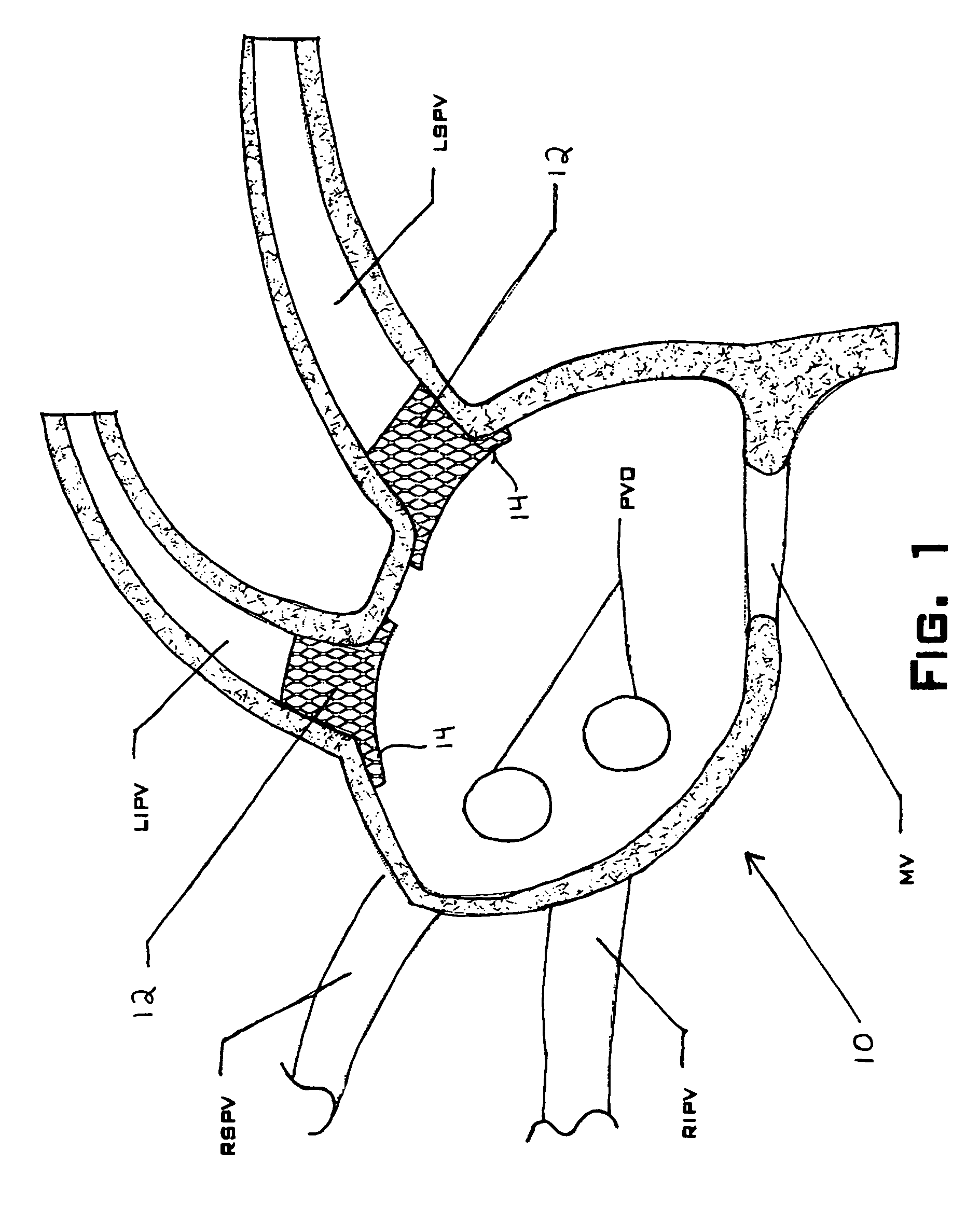
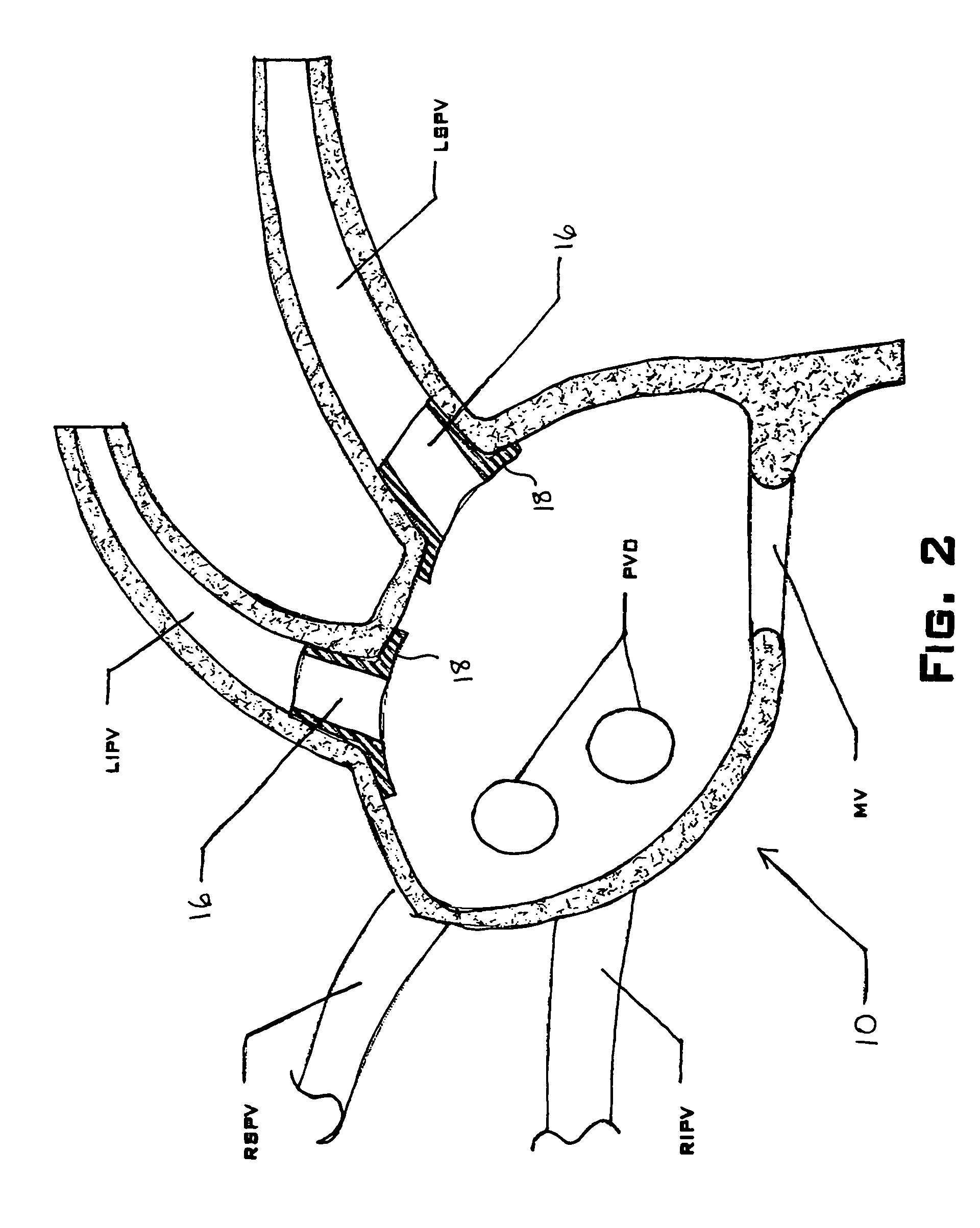
[0035]FIG. 1 shows a preferred use of an embodiment of a structure 10 of the present invention. The structure 10 in this embodiment is a stent 12 deployed in both the left inferior pulmonary vein (LIPV) and the left superior pulmonary vein (LSPV). The stent 12 includes a flared end 14 that is constructed and arranged to extend past the ostium of the the pulmonary vein and into the left atrium (LA).

[0036]The stent 12 is preferably constructed and arranged to maintain an outward force on the endothelium of the pulmonary vein and the left atrium, thus keeping the stent 12 in place and operating to prevent electrical communication between the pulmonary vein and the left atrium. The outward force is obtained through the use of an expandable stent, such as a self-expanding or mechanically expanding stent. The outward force necessary is dependent on the principal being practiced to prevent the electrical communication between the pulmonary vein and the left atrium.

[0037]For example, one me...


PUM

PropertyMeasurementUnit
Flow rateaaaaaaaaaa
Structureaaaaaaaaaa
Electrical conductoraaaaaaaaaa

Abstract

A method and device for the treatment of atrial fibrillation by inhibiting the flow of electricity from the pulmonary vein to the left atrium. The method includes inhibiting electrical flow by disabling the conductive fibers mechanically, using an incision (70), or via fibrosis, or chemically by applying toxic substances to the fibers. In one embodiment, a device (30) is useable to deliver a prosthetic structure (10) to the pulmonary vein that is useable to stretch the pulmonary vein, thereby inducing fibrosis, keeping the incision (70) open, or delivering a substance to the endothelium of the pulmonary vein. The structure (10) delivered by the device (30) is a self-expanding prosthetic structure. In another embodiment, a device (60) is useable to deliver and expand a prosthetic structure (10) that is expandable but not self-expanding.

Description

CROSS REFERENCE TO RELATED APPLICATIONS[0001]This application claims priority from provisional patent application Ser. No. 60 / 425,142, filed Nov. 8, 2002.BACKGROUND OF THE INVENTION[0002]This invention relates generally to methods and devices used to treat arrhythmias. In particular, this invention relates to treatment of paroxysmal atrial fibrillation by electrical isolation of the pulmonary veins from the left atrium of the heart.[0003]Atrial fibrillation is the most common form of cardiac arrhythmia and affects approximately 1.5 million patients in the United States annually, causing considerable morbidity as well as mortality. Additionally, atrial fibrillation is the leading cause of embolic stroke, leading to over 70,000 cerebrovascular failures per year.[0004]There is extensive literature documenting the role of the pulmonary veins as the origin of excitatory impulses in patients with paroxysmal atrial fibrillation. There is a 70% cure rate in the treatment of paroxysmal atria...

Claims


Application Information

Patent Timeline
IPC IPC(8): A61F7/00A61B18/18A61B19/00A61F2/00A61F2/82A61F11/00A61M
CPCA61F2/91A61F2/958A61F2310/0097A61F2250/0039A61F2002/821
Inventor MARGOLIS, JAMES R.
Owner MARGOLIS JAMES R
Learn More