Breathing apparatus

a technology of breathing apparatus and air intake valve, which is applied in the direction of operating means/releasing devices of valves, respirators, functional valve types, etc., can solve the problems of unnecessarily increasing electric power consumed by the blower, reducing the exhaustion of filtration materials and power consumption of the motor, and reducing the risk of pressure rising inside the facepiece and exhalation resistance increasing during exhalation. , the effect of reducing the risk of pressure rising inside the fa

Inactive Publication Date: 2007-03-27
KOKEN CO LTD
View PDF19 Cites 17 Cited by
  • Summary
  • Abstract
  • Description
  • Claims
  • Application Information

AI Technical Summary

Benefits of technology

[0020]The motor serving to drive the blower operates in a normal mode only during inhalation and does not operate or operates at a low speed during exhalation, based on the signals from the sensor. Therefore, the exhaustion of the filtration material and power consumption by the motor can be reduced. Moreover, the risk of pressure rising inside the facepiece and exhalation resistance increasing during exhalation is eliminated.
[0021]In the breathing apparatus in accordance with the present invention, control signals for the motor are generated using the operation of the exhalation valve or inhalation valve originally provided in the breathing apparatus. Therefore, the structure is simple and parts that are brittle or easy to deform, such as the diaphragms, are not required which results in improved resistance to breakdown.

Problems solved by technology

However, filtration materials such as filters, absorption canisters, and the like, with good purification efficiency typically have a large draft resistance.
People wearing dust masks provided with such filtration materials have difficulty in breathing normally by using only the capacity of their lungs.
However, the following problems are associated with such conventional technology.
However, if the voltage supplied to the blower is set such that the ventilation amount of the blower is no less than the maximum draft volume, the electric power consumed by the blower unnecessarily increases and the exhaustion of the filtration material is accelerated.
Further, because the filtration materials with a high draft resistance require blowers with a high torque, the consumption of electric power increases in proportion to the draft resistance of the filtration material used.
As a result, the mask structure is very complex and the differential pressure sensor is difficult to mount in a compact manner.
Further, because the opening of the first channel or second channel had to be provided between the filter and the fan, the size of the entire breathing apparatus was inevitably increased.
Further, a diaphragm is used as the pressure-responsive member, but the diaphragm is easily fatigued or damaged and the set values of the reaction pressure of the differential pressure sensor are difficult to maintain.

Method used


Image

  • Breathing apparatus
  • Breathing apparatus
  • Breathing apparatus

Examples


first embodiment

[0031]the present invention will be described hereinbelow with reference to FIGS. 1 through 4.

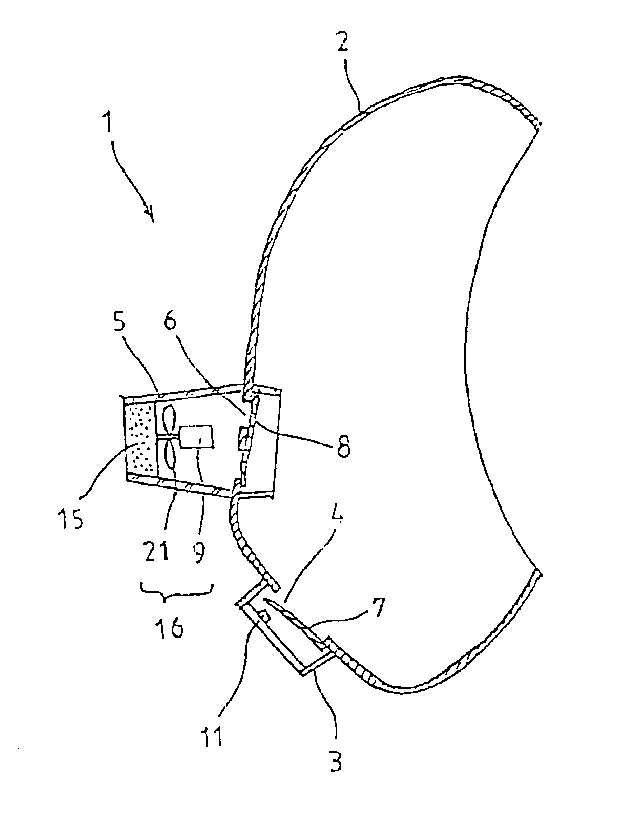
[0032]As shown in FIG. 1, an exhalation opening 4 and an inhalation opening 6 are formed in a facepiece 2 of a breathing apparatus 1. The exhalation opening 4 is covered on the outer surface thereof with an exhalation valve cover 3 provided on the facepiece 2.

[0033]Further, the inhalation opening 6 is covered on the outer surface thereof with a filtration material cover 5 provided on the facepiece 2.

[0034]An exhalation valve 7 which is open during exhalation and closed during inhalation is provided in the exhalation opening 4. On the other hand, an inhalation valve 8 which is closed during exhalation and open during inhalation is provided in the inhalation opening 6.

[0035]A filtration material 15 and a blower 16 are disposed opposite each other inside the filtration material cover 5 on the outer side of the inhalation valve 8. The blower 16 is composed of an impeller 21 and a motor 9 for ro...

second embodiment

[0045]the present invention will be described below with reference to FIG. 5.

[0046]The inner surface of the inhalation opening 6 formed in the facepiece 2 of the breathing apparatus is covered with the inhalation valve cover 20 provided on the facepiece 2. The inhalation valve 8 is disposed inside the inhalation valve cover 20. During inhalation, the inhalation valve 8 moves so as to recede from the inhalation opening 6 and introduces the outside air through the inhalation opening 6. During exhalation, the valve moves so as to approach the inhalation opening 6, comes in tight contact with the inhalation opening 6, and closes the inhalation opening 6.

[0047]The photointerrupter 11 is mounted on the surface of the inhalation valve cover 20 which faces the inhalation valve 8. The photointerrupter 11 is composed of a light-emitting diode and a transistor receiver, similarly to the first embodiment.

[0048]If the inhalation valve 8 is open and approaches the surface of the inhalation valve ...

third embodiment

[0053]the present invention will be described below with reference to FIG. 6.

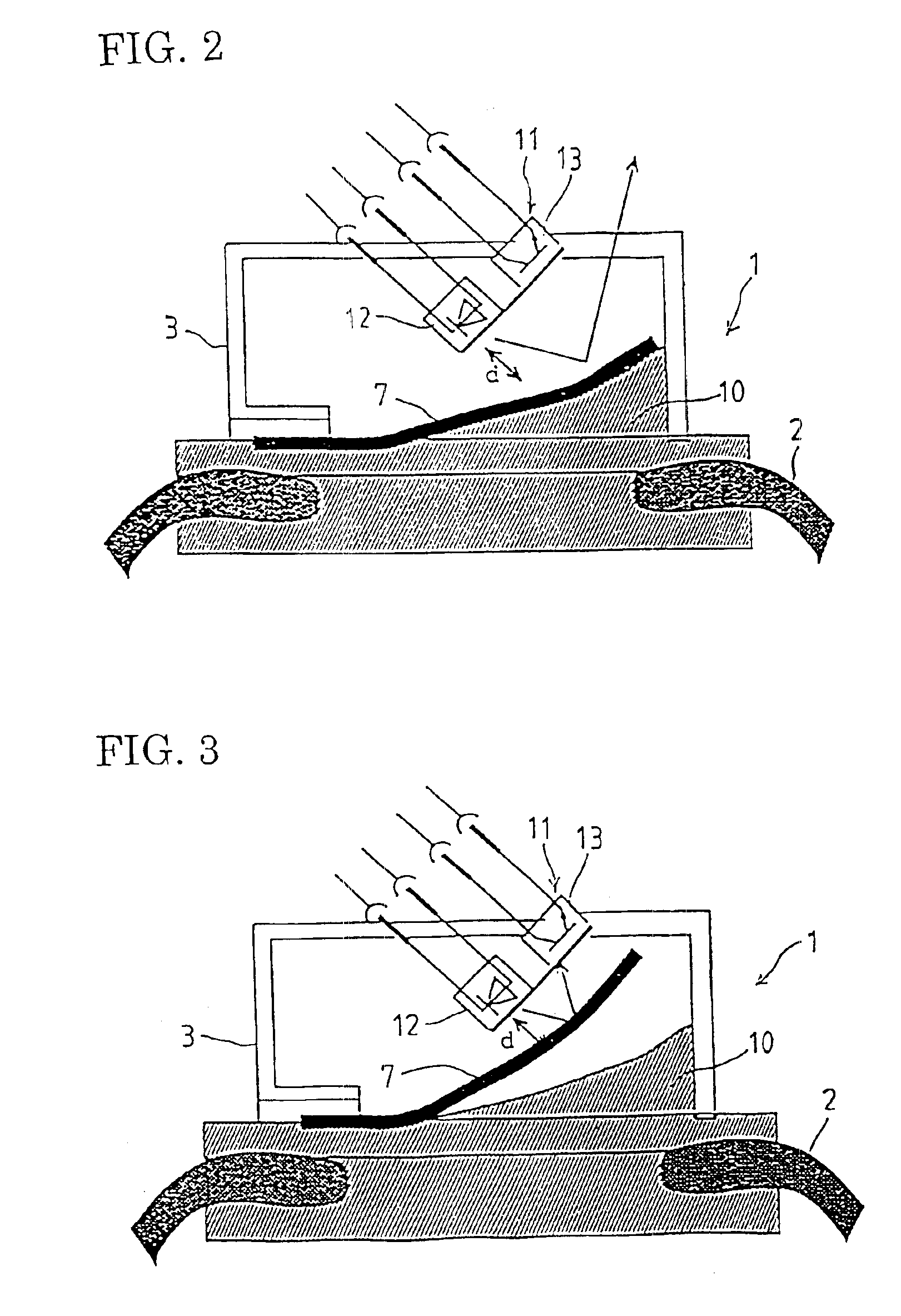
[0054]Both the exhalation valve 7 and the exhalation valve seat 10 are formed from an electrically conductive material such as an electrically conductive rubber or the like or from an electrically conductive material subjected to processing inducing electric conductivity. The exhalation valve seat 10 is mounted on the facepiece of the breathing apparatus upon splitting into at least two parts. A plus pole is formed on one of the two parts of the exhalation valve seat 10 and a minus pole is formed on the other part.

[0055]The exhalation valve seat 10 functions as a sensor sensitive to the movement of the exhalation valve 7. During inhalation, the exhalation valve 7 is closed and brought in contact with the exhalation valve seat 10. In this state, the plus pole and minus pole of the exhalation valve seat 10 are connected to each other via the exhalation valve 7, causing electric current (signal) to flow. As a ...


PUM


Abstract

An inhalation opening 6 and an exhalation-opening 4 are formed in the facepiece 2 of a breathing apparatus 1 and the openings can be closed with an inhalation valve 8 and exhalation valve 7, respectively. If a person wearing the breathing apparatus 1 inhales, the inhalation valve 8 is open and the exhalation valve 7 is closed. A photointerrupter 11 senses the closing operation of the exhalation valve 7 and supplies electric power to a motor 9 to drive a blower 16.

Description

BACKGROUND OF THE INVENTION[0001]1. Field of the Invention[0002]The present invention relates to a breathing apparatus suitable for full-face masks and half-face masks used with the object of protecting from dust, gases, and the like.[0003]2. Description of the Related Art[0004]People working in the atmosphere containing hazardous dust or toxic gases usually wear a dust mask or a gas mask and inhale a purified air after the hazardous and toxic substances contained in the air have been removed-with a filtration material such as active carbon or a filter contained in the dust mask.[0005]However, filtration materials such as filters, absorption canisters, and the like, with good purification efficiency typically have a large draft resistance.[0006]In particular, because penetration of radioactive dust present in nuclear power plants, dioxin-containing toxic dust in decomposition sites of incinerators, and toxic gases generated in a variety of other industrial operations into a human bo...

Claims


Application Information

Patent Timeline
Patent Type & Authority Patents(United States)
IPC IPC(8): A62B7/10A61M16/00A62B9/00A62B18/00A62B18/10F16K15/16F16K37/00
CPCA62B18/10A62B18/006A62B7/00
Inventor KURIYAMA, SATOSHI
Owner KOKEN CO LTD
Why Eureka
Try Eureka