Composite pressure tank and process for its manufacture

a technology of pressure tank and composite material, which is applied in the direction of vessel construction details, transportation and packaging, mechanical equipment, etc., can solve the problems of high thermal stress at the interface, rupture of the vessel, and the thermal stress problem of composite pressure vessels with metallic liners, etc., and achieve the effect of high cost and low weigh

Inactive Publication Date: 2007-03-27
MICROCOSM INC
View PDF5 Cites 22 Cited by
  • Summary
  • Abstract
  • Description
  • Claims
  • Application Information

AI Technical Summary

Benefits of technology

[0009]The vessel further comprises a skirt at each end of the vessel, extending cylindrically over a portion of each domed end. A cyrogenically compliant, adhesive shear ply is used at the skirt / dome y-joint area to reduce stress peaking at the interface.
[0010]Any of a variety of composite materials may be used for fabricating the liner shell and the outer surface of the vessel, including fiberglass and carbon in fabric and fiber form. The vessel may also include a coating of a cryogenically compliant material applied to the inside surface of the inner shell prevent micro-cracking of the inner surface during cryogenic applications and to reduce the permeability of the composite liner.
[0012]The step of assembling the two half portions of the liner shell includes forming an annular inner bellyband of composite material. The inner bellyband has an outside diameter selected to fit along the inside surface of the liner shell. The step of assembling the two half portions further includes bonding the inner bellyband with adhesive onto one of the shell halves, leaving half of the axial length of the inner bellyband protruding from the liner half; securing the protruding part of the inner bellyband with adhesive to the other shell half; and then forming an outer bellyband of composite material around the liner shell, to strengthen the joint between the two halves and to complete their assembly.
[0015]It will be appreciated from the foregoing summary that the present invention represents a significant advance in the field of pressure vessel fabrication for cryogenic, space and other applications. In particular, a vessel formed by overwrapping a composite liner shell with additional composite material has relatively low weight and low cost. Other aspects and advantages of the invention will become apparent from the following more detailed description, taken in conjunction with the accompanying drawings.

Problems solved by technology

Unfortunately, composite pressure vessels with metallic liners present a thermal stress problem, when used to store cryogenic materials.
Specifically, significant differences in the coefficients of thermal expansion (CTE), between the metallic liner and the composite outer shell, result in high thermal stresses at the interface.
These thermal stresses can be significant enough to cause rupture of the vessel if not addressed.
A vessel fabricated with only composite materials would obviate the disadvantages of using a metallic liner.
Composite pressure vessels for aerospace applications can be very expensive due largely to the need for an autoclave.
Autoclaves control the temperature and pressure during curing and can be expensive devices, especially if the vessels to be manufactured are large.

Method used


Image

  • Composite pressure tank and process for its manufacture
  • Composite pressure tank and process for its manufacture
  • Composite pressure tank and process for its manufacture

Examples


Embodiment Construction

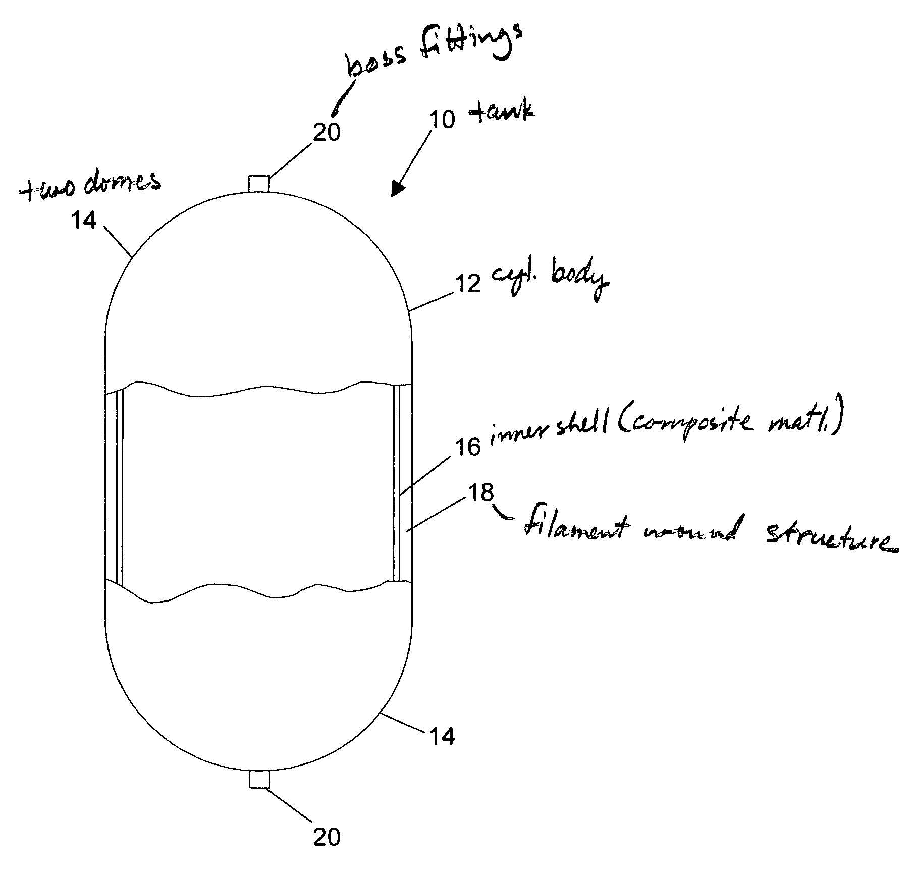
[0041]As shown in the drawings for purposes of illustration, the present invention pertains to pressure vessels for use in applications in which weight, cost, or both are important concerns. Although the invention was made with launch vehicle propellant tanks and other space vehicle applications in mind, it may also be usually applied in other fields. In the past, pressure vessels of this general type have been made to include a metal liner, or have been made in part from composite materials that must be cured the controlled temperature and pressure environment of an autoclave.

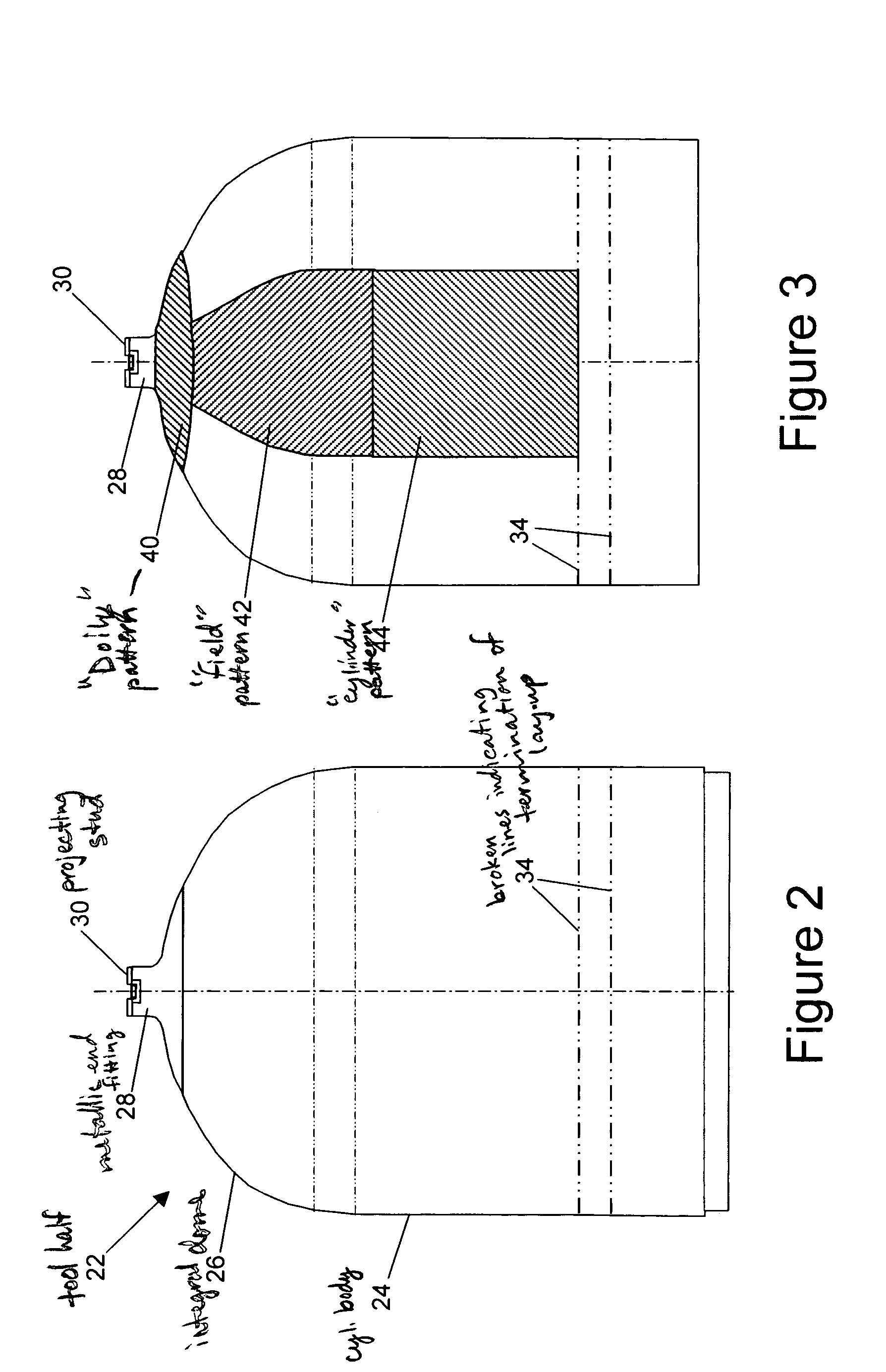
[0042]In accordance with the present invention, a pressure vessel is formed to include an inner shell of a composite material, which is then filament wound with an outer composite structure and cured out-of-autoclave. Most pressure vessels are either spherical or cylindrical in shape. The one described here by way of example is cylindrical with domed, geodesic, iso-tensoid dome profiles. However, for convenien...


PUM

PropertyMeasurementUnit
fiber angleaaaaaaaaaa

Abstract

A pressure vessel (10) and a process for its fabrication, the vessel (10) having a liner shell (16) formed from composite materials cured out-of-autoclave, and an outer structure (18) formed by winding or laying up additional layers of composite material over the liner shell. The liner shell (16) is formed as two halves, each with an opening into which a boss fitting (20) is installed. The two halves may be separately formed by a lay-up process, or first formed as a whole liner shell by filament winding, the whole liner shell then being cut in half to permit installation of the boss fittings (20). After curing, the halves are assembled and the outer structure (18) is wrapped over the liner shell (16) and also cured out-of-autoclave. The resulting pressure vessel (10) can be used for reliable storage of cryogenic or other materials, yet is light in weight and not costly.

Description

[0001]This invention was made with Government support under Contract Number F29601-01C-0069 awarded by the United States Air Force. The Government has certain rights in the invention.BACKGROUND OF THE INVENTION[0002]This invention relates generally to pressure vessels and, more particularly, to pressure vessels used for storage of cryogenic and other materials in rocket launch vehicles and space applications. In aerospace applications, pressurized propellant tanks may be fabricated by filament winding fiber reinforcement over a thin walled metallic liner. Carbon or fiberglass fibers provide the required strength without the weight penalty associated with an all-metallic tank. Unfortunately, composite pressure vessels with metallic liners present a thermal stress problem, when used to store cryogenic materials. Specifically, significant differences in the coefficients of thermal expansion (CTE), between the metallic liner and the composite outer shell, result in high thermal stresses...

Claims


Application Information

Patent Timeline
Patent Type & Authority Patents(United States)
IPC IPC(8): B65D25/14
CPCF17C1/04F17C2270/0197F17C2201/054F17C2201/056F17C2203/0604F17C2203/0607F17C2203/0619F17C2203/0636F17C2203/0663F17C2203/0665F17C2203/067F17C2205/0323F17C2205/0397F17C2209/21F17C2209/2109F17C2209/2154F17C2209/227F17C2209/228F17C2209/23F17C2221/08F17C2223/0161F17C2223/033F17C2260/012F17C2260/035F17C2270/0186F17C2270/0194F17C2201/0109
Inventor CUNDIFF, ROY S.MANCUSO, ANTHONY
Owner MICROCOSM INC
Why Eureka
Try Eureka