Optical data recording medium and manufacturing method for the same

Active Publication Date: 2007-03-27
PANASONIC CORP
View PDF21 Cites 10 Cited by
  • Summary
  • Abstract
  • Description
  • Claims
  • Application Information

AI Technical Summary

Benefits of technology

[0045]Uniformity at the same radius in the radiation curable resin placed by the spin coating method is thus eliminated and a layer with uniform thickness can be achieved.
[0046]Preferably, an adhesive ma

Problems solved by technology

A short wavelength and high NA, however, decrease the tolerance for tilt, i.e., an inclination of the disc to the incidence angle of the laser beam.
Unfortunately, it is difficult with conventional spin coating techniques to apply the resin material with a uniform thickness from the inside circumference side to the outside circumference side of the disc.
Multilayer discs as described above have very low tolerance to variation in the thickness of the layers that must be passed by the read/write laser.
Furthermore, because the re

Method used


Image

  • Optical data recording medium and manufacturing method for the same
  • Optical data recording medium and manufacturing method for the same
  • Optical data recording medium and manufacturing method for the same

Examples


first embodiment

[0089]A manufacturing method for an optical data recording medium according to a first embodiment of the present invention is described first below with reference to FIG. 1 to FIG. 3. The manufacturing method for this optical data recording medium broadly includes the following processes.

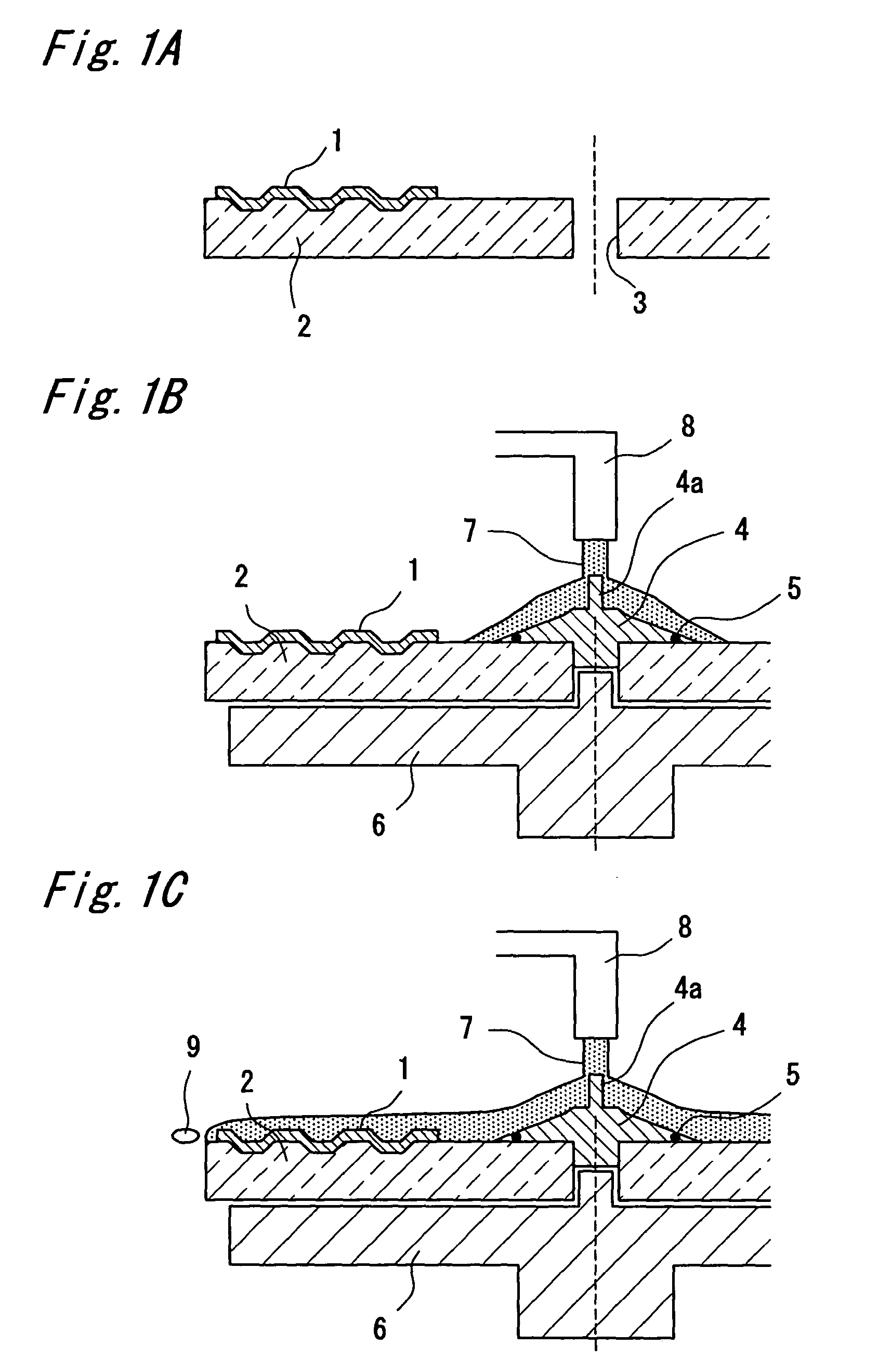
[0090](a) First, as shown in FIG. 1A, a substrate 2 that is 1.1 mm thick, 120 mm in diameter, and has a data recording layer 1 on one side (referred to below as the “recording-layer-side surface”) is prepared. A 15 mm diameter center hole 3 is formed through the thickness direction of the substrate 2 in the center of this substrate 2.

[0091](b) Then, as shown in FIG. 1B, the substrate 2 is placed on a rotary table 6 with the recording-layer-side surface facing up, and the center hole 3 is then closed from above with a cap 4. The cap 4 is metal and has a seal ring 5 made of Teflon (R), for example, formed where the cap 4 contacts the recording-layer-side surface of the substrate 2. A stud 4a is dispos...

second embodiment

[0126]An optical disc manufacturing method according to a second embodiment of the present invention is described next with particular reference to FIG. 4 and FIG. 5.

[0127]This embodiment differs from the optical disc manufacturing method of the first embodiment in that the positions of the substrate 2 and stamper 11 are reversed, the radiation curable resin is coated to the stamper 11, and the substrate 2 is then pressed to the resin-coated stamper 11.

[0128]In addition, the seal ring 5 is not provided on the cap 4. Instead, a magnet is disposed to the cap 4 so that the cap 4 is attracted to a corresponding magnet disposed to the rotary table 6 to improve adhesion and the seal between the cap 4 and substrate 2.

[0129]The optical disc manufacturing method of this embodiment is described in detail next.

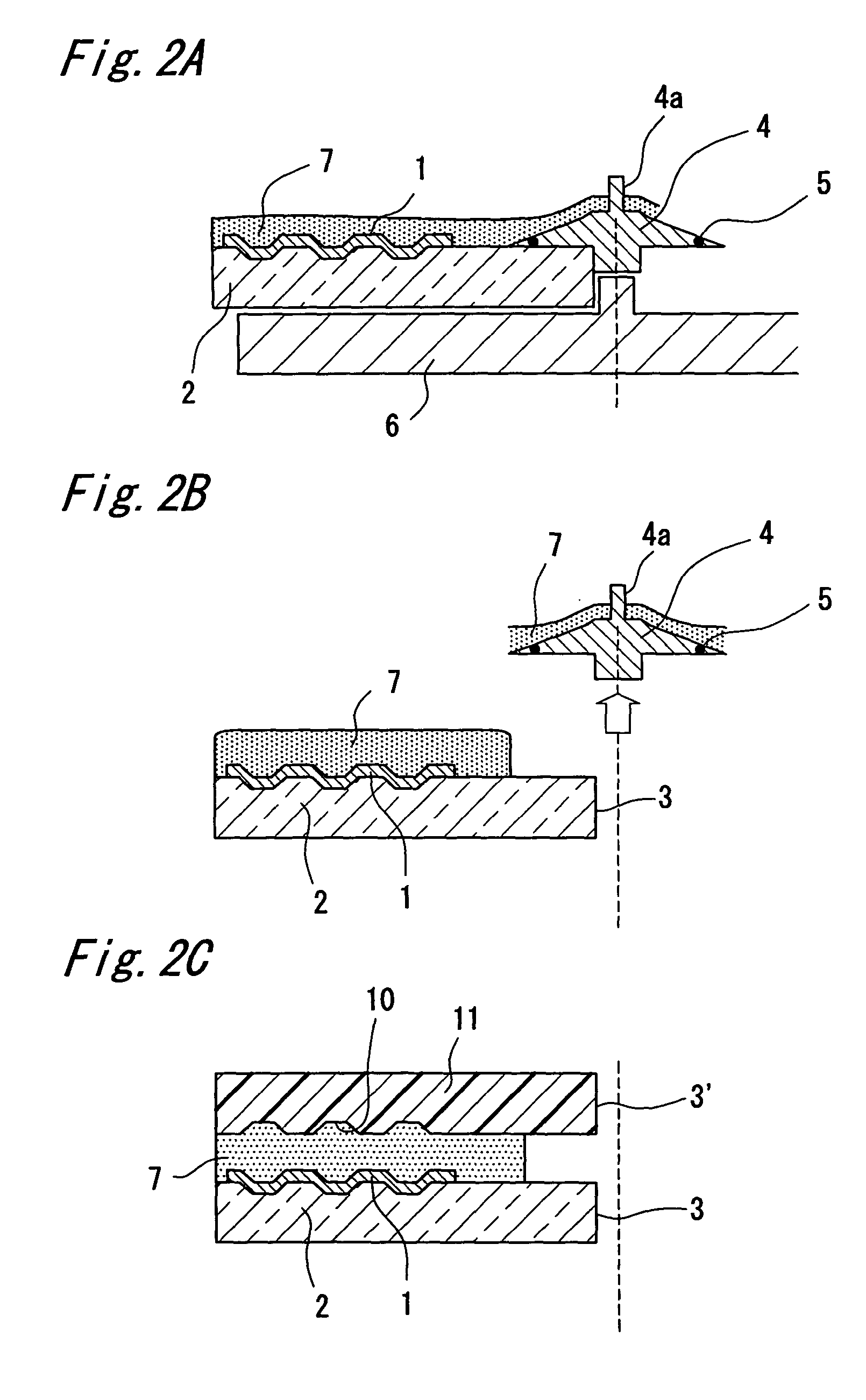
[0130](a) First, as shown in FIG. 4A, a stamper 11 with center hole 3′ and pits 10 is prepared as described in the first embodiment above.

[0131](b) The stamper 11 is then placed on the r...

third embodiment

[0141]An optical disc manufacturing method according to a third embodiment of the present invention is described next with particular reference to FIG. 6 and FIG. 7.

[0142]This embodiment differs from the first embodiment in the formation of the intermediate layer of the two layer structure.

[0143]This optical disc manufacturing method is described below.

[0144](a) A radiation curable resin 7 layer is first formed on the substrate 2 as in the optical disc manufacturing method of the first embodiment (see FIGS. 1A to 1C and FIG. 2). The thickness of the radiation curable resin 7 layer, however, is thinner than in the first embodiment.

[0145](b) Next, as shown in FIG. 6A, the stud 4a of the cap 4 is held and pulled upward to move the cap 4 straight up and away from the substrate 2 (i.e., the stud 4a is pulled up to remove the cap 4 from the substrate 2).

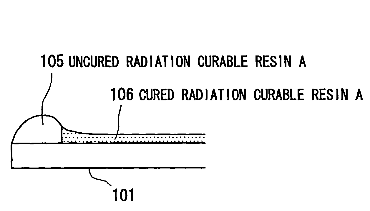
[0146](c) The radiation curable resin 7 on the substrate 2 is then exposed to radiation (such as UV light) to cure the resin and form cur...


PUM

PropertyMeasurementUnit
Fractionaaaaaaaaaa
Thicknessaaaaaaaaaa
Radiusaaaaaaaaaa

Abstract

An optical disc manufacturing method suppresses thickness variation in intermediate layers disposed between any two data recording layers to achieve an intermediate layer of uniform thickness. A substrate having a center hole and data recording layer is first prepared. This center hole is then plugged with a capping member and a resin material is dripped from above the center hole while spinning the substrate around its center hole to coat the data recording layer with the resin by a spin coating method. The capping member is then removed. Then, a stamper having a groove or lands and pits on its surface is prepared. The groove or lands and pits side of the stamper is then pressed into the resin material on the substrate, and the resin is then cured to form an intermediate layer. The stamper is then separated from the substrate to leave a data recording layer in the surface of the intermediate layer with a groove or land-and-pit pattern corresponding to the groove or lands and pits in the stamper.

Description

BACKGROUND OF THE INVENTION[0001]1. Field of the Invention[0002]The present invention relates to an optical data recording medium having two or more data recording layers, and to a manufacturing method for this optical data recording medium.[0003]2. Description of Related Art[0004]Optical data recording media such as optical discs are quickly becoming the information recording medium of choice for a wide range of applications. Common types of optical discs include read-only, incrementally writable (e.g., multisession), and rewritable media. Compact Discs (CDs) used for distributing packaged audio content and Laser Discs for recording video data (such as movies) are typical read-only optical discs. Multisession CDs for storing text files and still images, for example, are typical of incrementally writable media. Rewritable media include a variety of recordable discs for storing personal computer data files and other types of content.[0005]One advantage of optical media is that optica...

Claims


Application Information

Patent Timeline
IPC IPC(8): B32B37/00B29D17/00G11B7/24G11B7/24038G11B7/24056G11B7/26
CPCB29D17/005G11B7/266G11B7/263G11B7/24G11B7/26
Inventor HISADA, KAZUYAOHNO, EIJIHAYASHI, KAZUHIRO
Owner PANASONIC CORP
Why Eureka
Try Eureka