[0032]The present invention is a computational
geometric design system that is capable of sufficiently efficient computations so as to allow real-time deformations to objects such as surfaces while a user is supplying the object modifying input. Thus, the present invention is a paradigm shift away from typical CAD systems since, in a typical
CAD system the user must supply input for changing or modifying a geometric object and subsequently explicitly request
processing of the input to commence. Thus, in such prior art CAD systems, the user receives feedback about his / her design at discrete user requested times. Instead, with the present invention, updates may be processed in real-time immediately upon input
receipt without the user explicitly indicating that update
processing is to be performed.
[0033]Given the enhanced computational efficiency of the present invention, a user of the present invention can more efficiently perform iterative approximations to a geometric object being designed. The user may speedily design without the need to precisely calculate design geometric characteristics for portions of the object where such precision may not be necessary. That is, the user can be less concerned about getting it “right the first time” since the ease of modification and speed of computing modifications allows the user to more rapidly approximate and / or prototype a geometric object. Thus, the present invention can have substantial efficiency benefits in that for many geometrically designed objects (including machined parts), substantial portions of such objects may be satisfactorily designed with a wide range of geometric characteristics.
[0041]It is also within the scope of the present invention that the geometric objects Si used to generate a blended geometric object S may be such that the Si's can be modified indirectly via other geometric objects from which the Si's may be themselves generated. For example, if S is a surface blended from isocline ribbons S1 and S2 (having corresponding profiles P1 and P2, respectively), and the ribbon S1 interpolated from the profile
handle, the isocline
handle, and the ribbon tangent at the end points of P1, then the present invention provides user interaction techniques for modifying such handles and / or ribbon tangents for thereby modifying the blended surface S. Moreover, in one
user interface technique, only the handles may be displayed, wherein such handles are displayed as connected to the blended surface S. Thus, by changing such handles, the blended surface changes. Note that such user interaction techniques may be responsive in real time to user changes to such handles and / or ribbon tangents. Thus, a user's
design intent may be immediately displayed while the user is inputting such changes. Accordingly, using the present invention, user interactions in the
design process may become closer to the techniques in used in constructing actual geometric models rather than prior art CAD user interaction techniques.
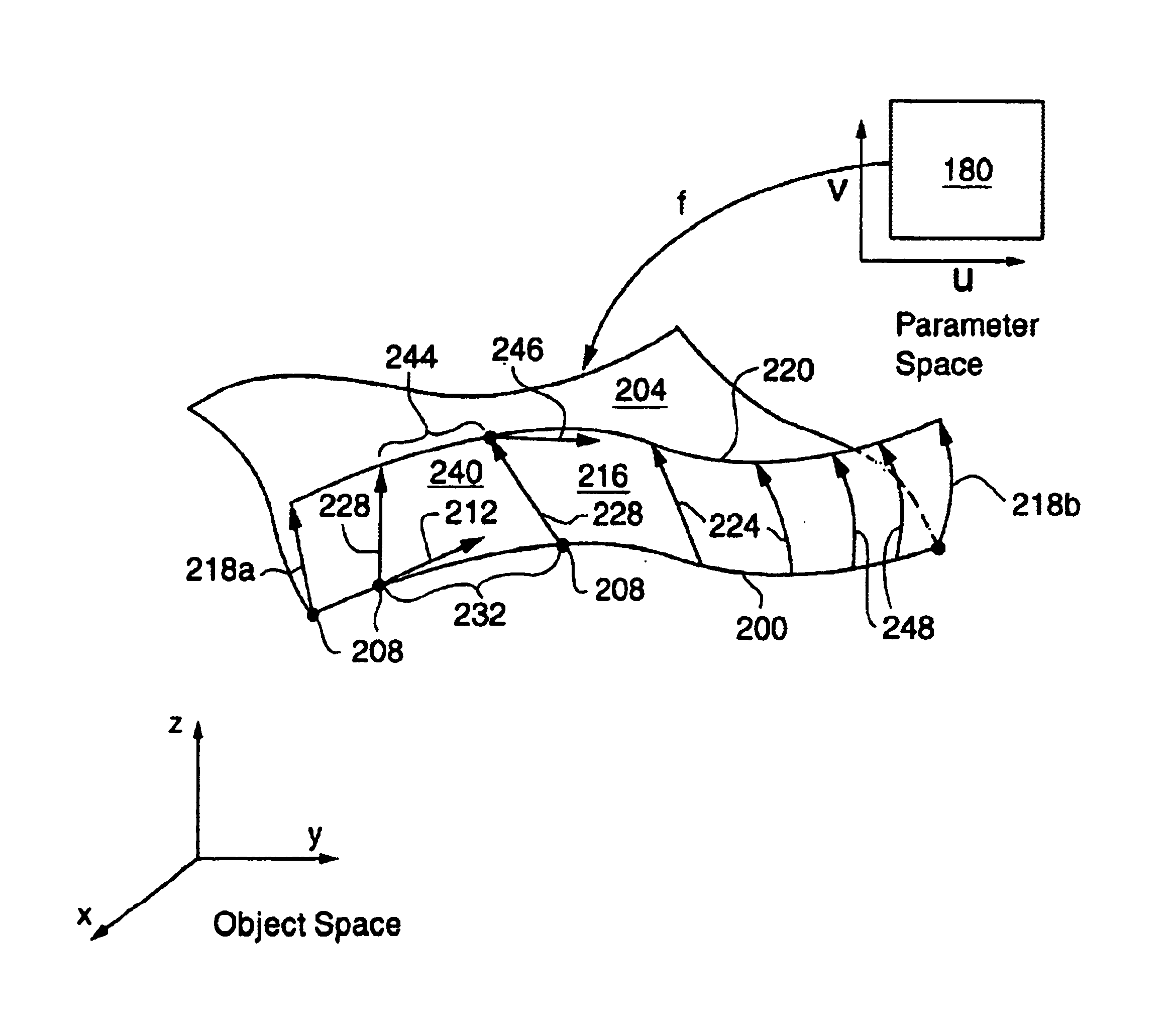
[0042]It is another aspect of the present invention that various geometric constraint criteria are capable of being applied to geometric objects generated according to the present invention. In particular, features and / or subgeometry of a geometric object O0 are capable of being constrained to lie within another geometric object, O1, so that as O1 is deformed, the features and / or subgeometry of O0 deform correspondingly, and thereby cause O0 to deform accordingly. For example, the present invention allows an object space point p to be defined (i.e., parameterized) so that it must remain in / on a given geometric object O1, where O1 may be a curve, surface, volume or
solid. Thus, as O1 is deformed, O0 also deforms. Moreover, instead of a point p, other geometric subobjects may also be similarly constrained, such as curves, surfaces or solids. Additionally, features of a geometric object O0 such as control points, handles (of various types, e.g., profile and isocline), normals, twist vectors, etc. may also be similarly constrained by the present invention so that as O1 is deformed, O0 is caused to also deform. For instance, using the geometric object interpolation techniques provided by the present invention, e.g., Formula (1) and variations thereof, the geometric object O0 can be efficiently regenerated (e.g., reinterpolated) substantially in real-time when constrained features and / or subgeometries of O0 are correspondingly deformed with a deformation of O1. More particularly, this aspect of the present invention provides for the combining of various geometric objects hierarchically so that geometric
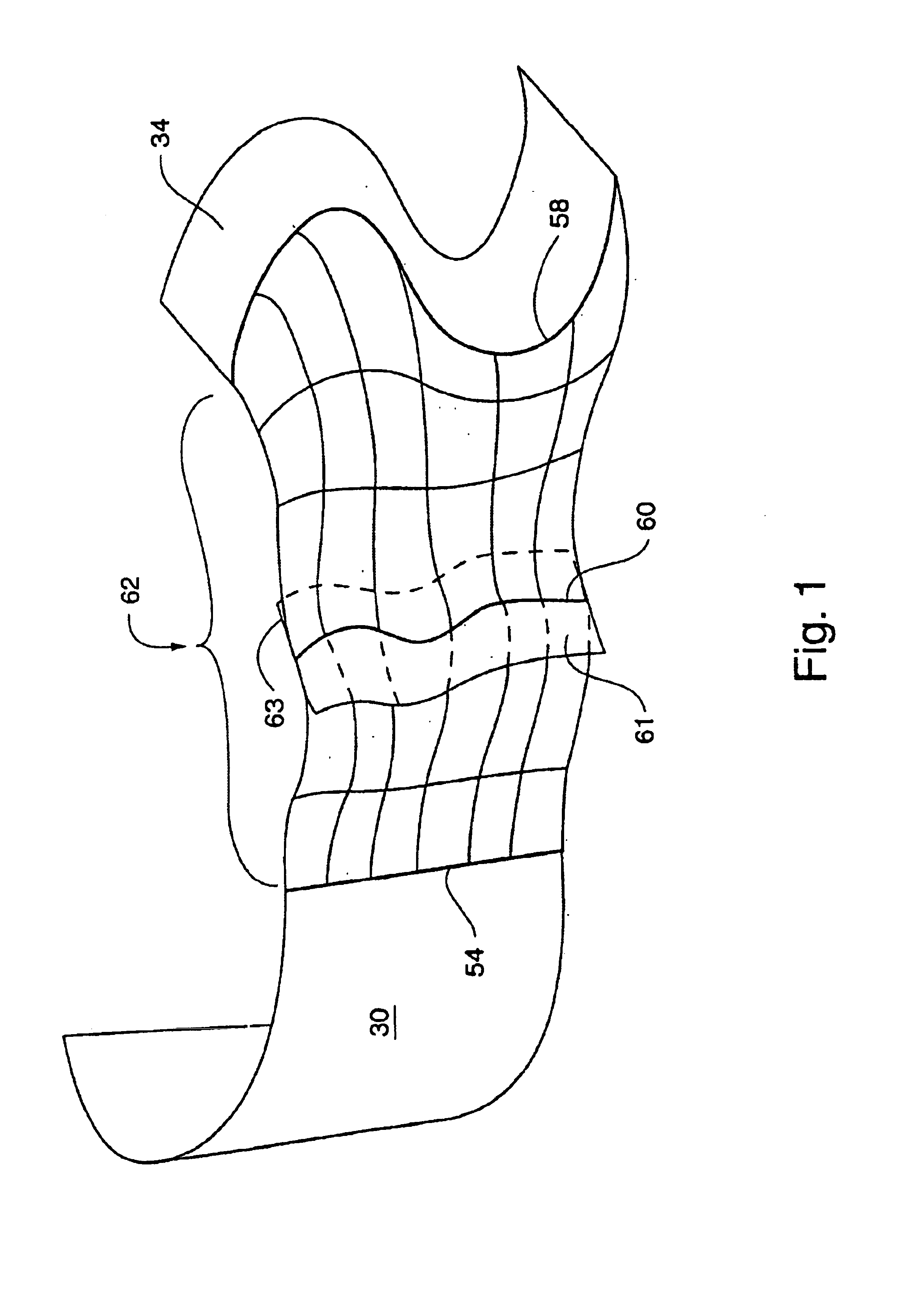
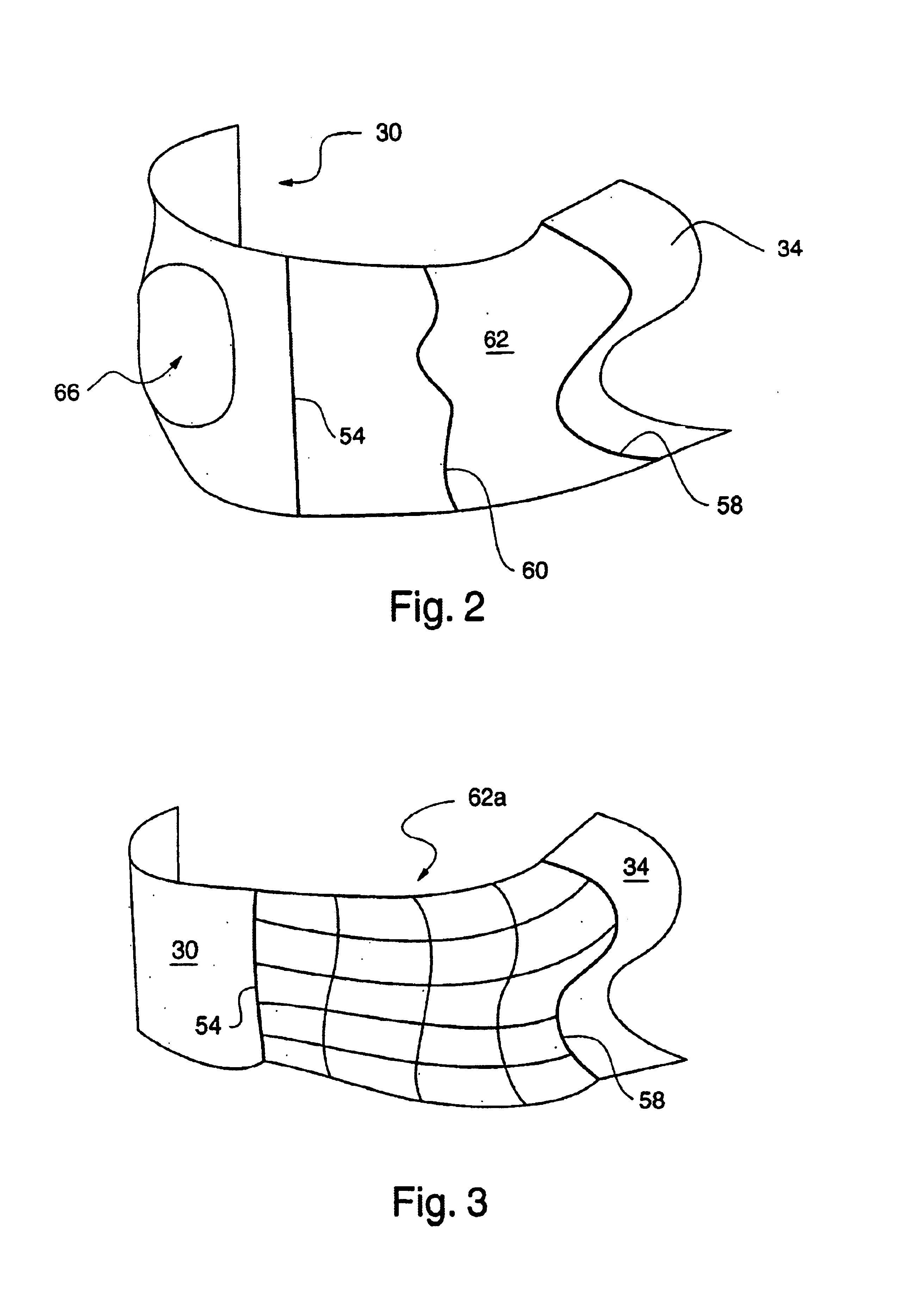
deformation control of a parent object causes corresponding geometric changes in dependent child geometric objects. For example, when a surface patch represents fine scale detail of a larger surface, it may be advantageous to attach the fine detail surface patch to the larger surface to thereby give a user
automatic control over the shape of the fine detail surface patch by controlling the shape of the larger surface. Moreover, similar hierarchical control can be provided with other geometric objects of types such as curves, points and three-dimensional deformation spaces.

