Optical ferrule

a technology of optical ferrules and ferrules, applied in the field of optical ferrules, can solve the problems of reducing alignment tolerance and more conventional packaging, and achieve the effect of improving light coupling

Inactive Publication Date: 2007-03-27
REFLEX PHOTONIQUE REFLEX PHOTONICS
View PDF9 Cites 50 Cited by
  • Summary
  • Abstract
  • Description
  • Claims
  • Application Information

AI Technical Summary

Benefits of technology

[0011]The optical ferrule has two opposite ends. The first end consists of the 45-degree bevel at the tips of the waveguides (optical fiber) and the second end is the flat-polish with alignment dowel pins. The 45-degree bevel at the tips of the waveguides (optical fiber) allows for side-coupling of light into the core of the waveguide (optical fiber) by using the 45-degree bevel as a mirror surface. The light is initially directed at 90-degrees to the longitudinal center axis of the optical fiber and travels through the cladding towards the center of the beveled tip. Total internal reflection at the 45-degree beveled tip forces the light to reflect at 90-degrees and couple along the longitudinal axis of the optical fiber. However, a metallic reflection coating can be applied to the beveled tip with an appropriate metal to enhance the coupling into the optical fiber. The flat-polish at the second end of the ferrule, along with the appropriate alignment dowel pins, allows a flat-polish (or angled polish) mating connector, such as the MPO / MTP™ parallel optical fiber connector, to mate with the other end of the waveguide (optical fibers) in the ferrule.
[0020]Preferably, the body has a beveled end opposite the connector end, light being coupled between a side coupling surface of the body, the beveled end and the fibers. Preferably, part of the cladding of the fibers is removed to improve light coupling.
[0023]1) The top half of the silicon v-groove chip that contains the optical fibers has been over-polished on the large 2-D surface such that the longitudinal length of the cladding of all the optical fibers has been slightly removed (between 0 and 25-microns). This allows a closer proximity to the core of the optical fibers.
[0025]3) Because the alignment pins are recessed with respect to the flat abutment surface and the external dowel pins are not initially inserted into the assembly, the flat abutment surface can be polished without obstructions to prepare the surface for mating with a standard optical connector.

Problems solved by technology

This method allows more conventional packaging and reduces the alignment tolerance because the length of the optical fiber is essentially laid over the flat surface of the PCB.

Method used


Image

  • Optical ferrule
  • Optical ferrule
  • Optical ferrule

Examples


Embodiment Construction

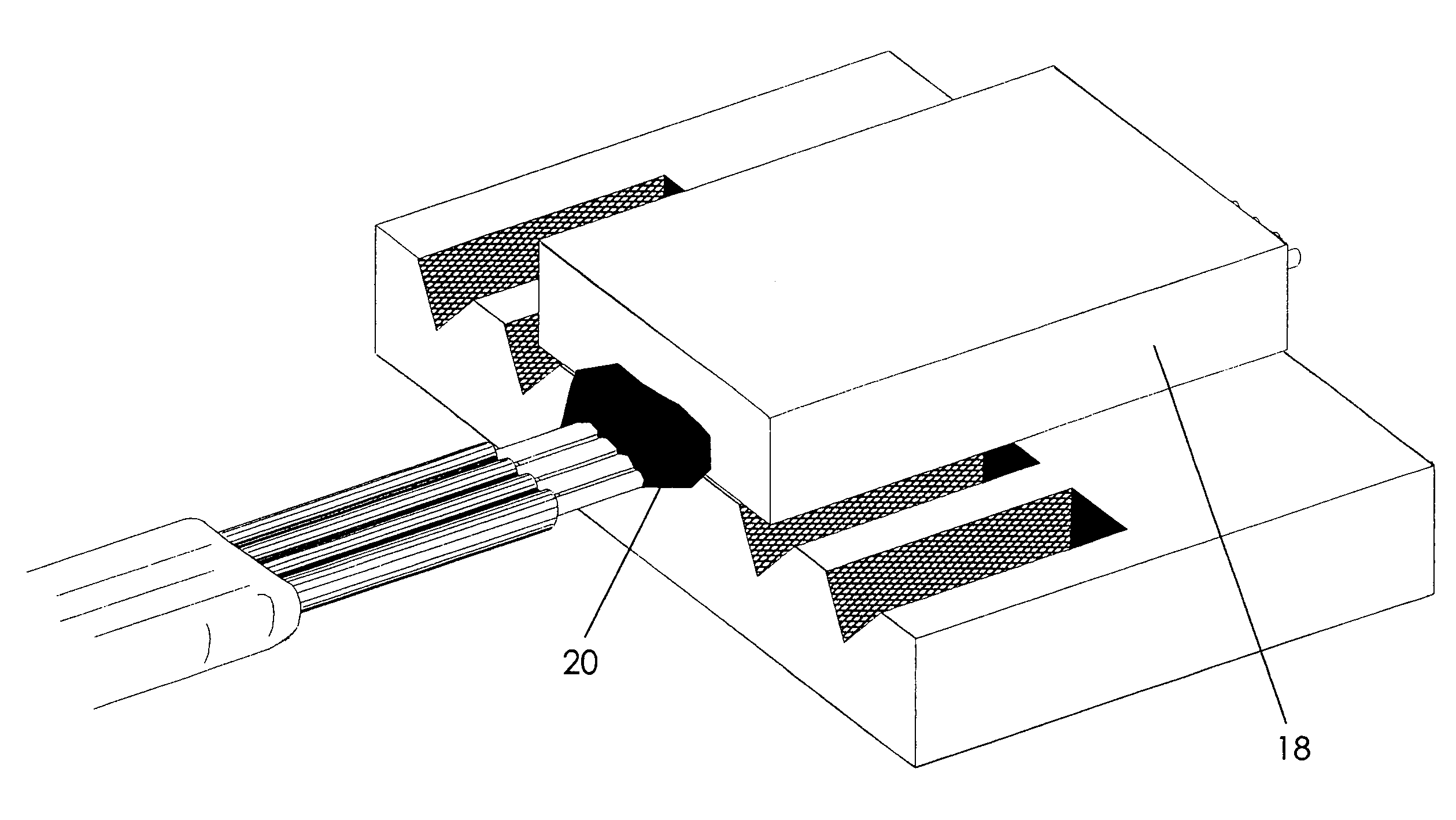
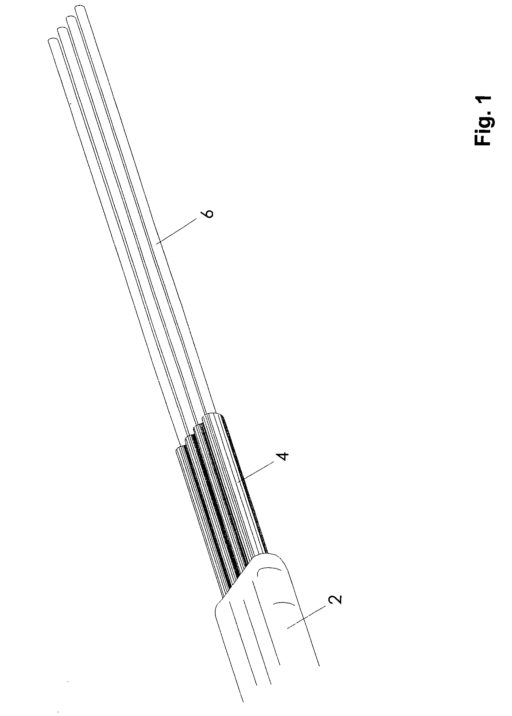
[0056]The parallel optical ferrule is a mechanical structure used to interface between a parallel optical fiber ribbon cable and an array of optoelectronic devices, such as a vertical cavity surface emitting laser (VCSEL) array or photodetector array.

[0057]The ferrule has two ends; one end interfaces with the optoelectronic device and the other end interfaces with a standard connector assembly such as the MPO / MTP™ parallel optical connector. Within the ferrule is a linear array of optical fibers that optically connects both ends of the ferrule.

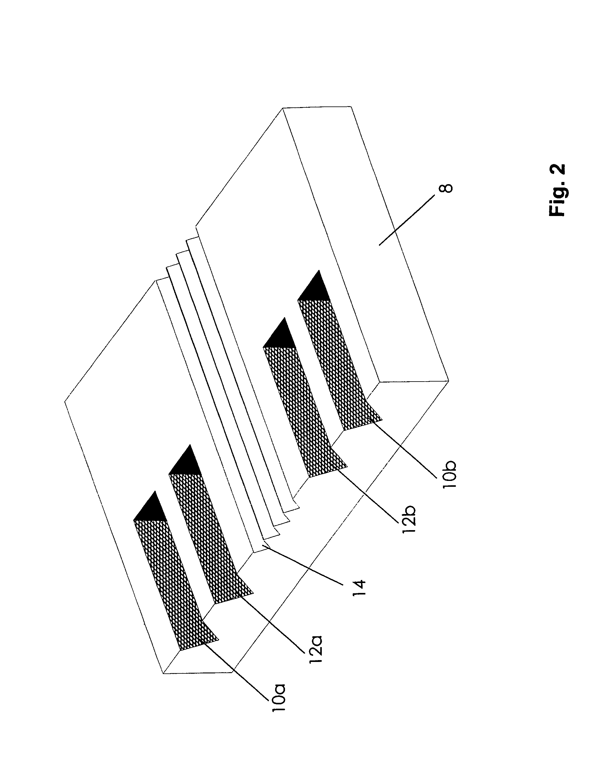
[0058]The first end of the ferrule is polished at a 45-degree angle to create a reflective glass-air interface at the fiber tips. This interface can reflect light at 90-degrees by either total internal reflection (TIR) when the glass-air interface is preserved, or by depositing a reflective metal layer on the exposed tips of the fiber. The reflective metal layer may be made of gold, silver, etc. The use of a reflective layer allows for the OE ...


PUM


Abstract

An optical connector and a manufacturing method are disclosed. The method for manufacturing an optical connector achieving a mechanical coupling comprises embedding a length of at least one optical fiber in a body to form an assembly. It also comprises to remove, at a first end of the assembly, a portion to provide a beveled surface on a corresponding first end of the optical fiber at which light is reflected for a side coupling. Also, at a portion of a side of the assembly near the first end, the method comprises creating an optical surface to provide a flat coupling surface for said side coupling. The method also comprises removing, at a second end of the assembly, a portion to provide a flat abutment surface including a corresponding second end of the at least one optical fiber. The method also comprises providing at the second end of the assembly a mating structure for precision connecting with a complementary connector in which an optical waveguide is end-coupled with at least one of the optical fiber.

Description

CROSS-REFERENCE TO RELATED APPLICATIONS[0001]This is the first application filed for the present invention. This application is related to commonly assigned co-pending applications filed herewith bearing Ser. No. 10,625,905 entitled “Optical Connector Assembly”, and Ser. No. 10 / 725,566 entitled “Encapsulated Optical Package”, the specifications of which are hereby incorporated by reference.TECHNICAL FIELD[0002]This invention pertains to the field of connecting devices. More precisely, this invention relates to the field of optical ferrules.BACKGROUND OF THE INVENTION[0003]This invention relates to the optical coupling of light emitted, absorbed or altered by optoelectronic devices, such as photodetectors, light emitting diodes, lasers, vertical cavity surface emitting lasers (VCSEL), etc., with optical waveguides, such as optical fibers, planar waveguides, etc., which can be further coupled to standard optical connector types such as the MPO / MTP™ connector.[0004]An optoelectronic ch...

Claims


Application Information

Patent Timeline
Patent Type & Authority Patents(United States)
IPC IPC(8): G02B6/00G02B6/38G02B6/42
CPCG02B6/3839G02B6/3885G02B6/4249G02B6/4214G02B6/421
Inventor ROLSTON, DAVID ROBERT CAMERONMAJ, TOMASZ
Owner REFLEX PHOTONIQUE REFLEX PHOTONICS
Why Eureka
Try Eureka