Sputter coating apparatus including ion beam source(s), and corresponding method

a technology of sputter coating and beam source, which is applied in the direction of vacuum evaporation coating, coating, electrolysis components, etc., can solve the problems of each of the aforesaid sputtering devices

Inactive Publication Date: 2007-04-03
GUARDIAN GLASS LLC
View PDF59 Cites 50 Cited by
  • Summary
  • Abstract
  • Description
  • Claims
  • Application Information

AI Technical Summary

Benefits of technology

[0010]In certain example embodiments of this invention, there is provided a coating apparatus which is capable of depositing a first coating (single or multi-layered) onto a first side of a substrate passing through the apparatus, and a second coating (single or multi-layered) onto the other or second side of the substrate passing through the apparatus. In certain example embodiments, the first coating

Problems solved by technology

Unfortunately, each of the aforesaid sputtering devices are problematic in that they can only coat one side of a substrate at a time.
This is unde

Method used


Image

  • Sputter coating apparatus including ion beam source(s), and corresponding method
  • Sputter coating apparatus including ion beam source(s), and corresponding method
  • Sputter coating apparatus including ion beam source(s), and corresponding method

Examples


Embodiment Construction

[0027]Referring now more particularly to the accompanying drawings in which like reference numerals indicate like parts throughout the several views.

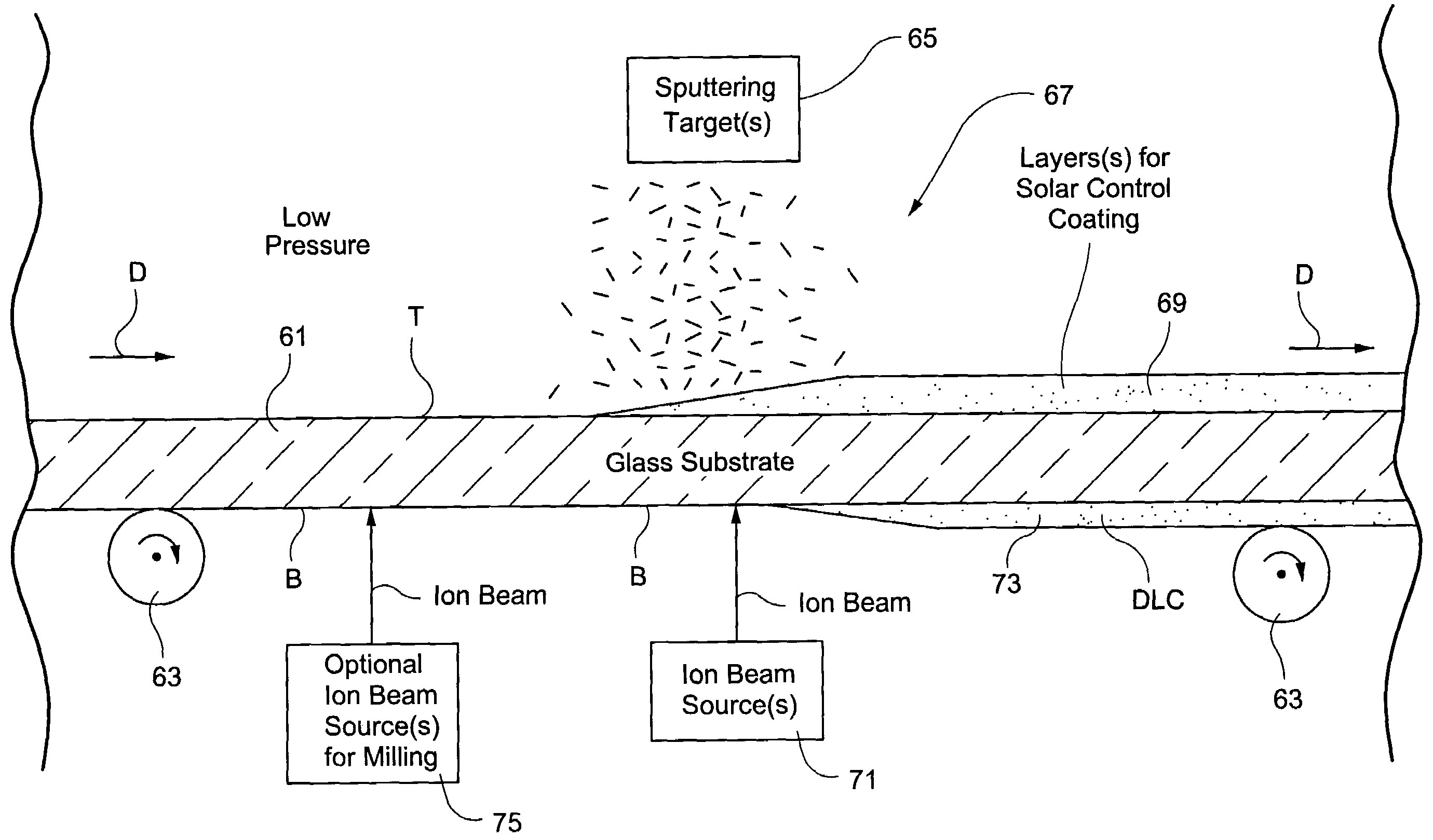
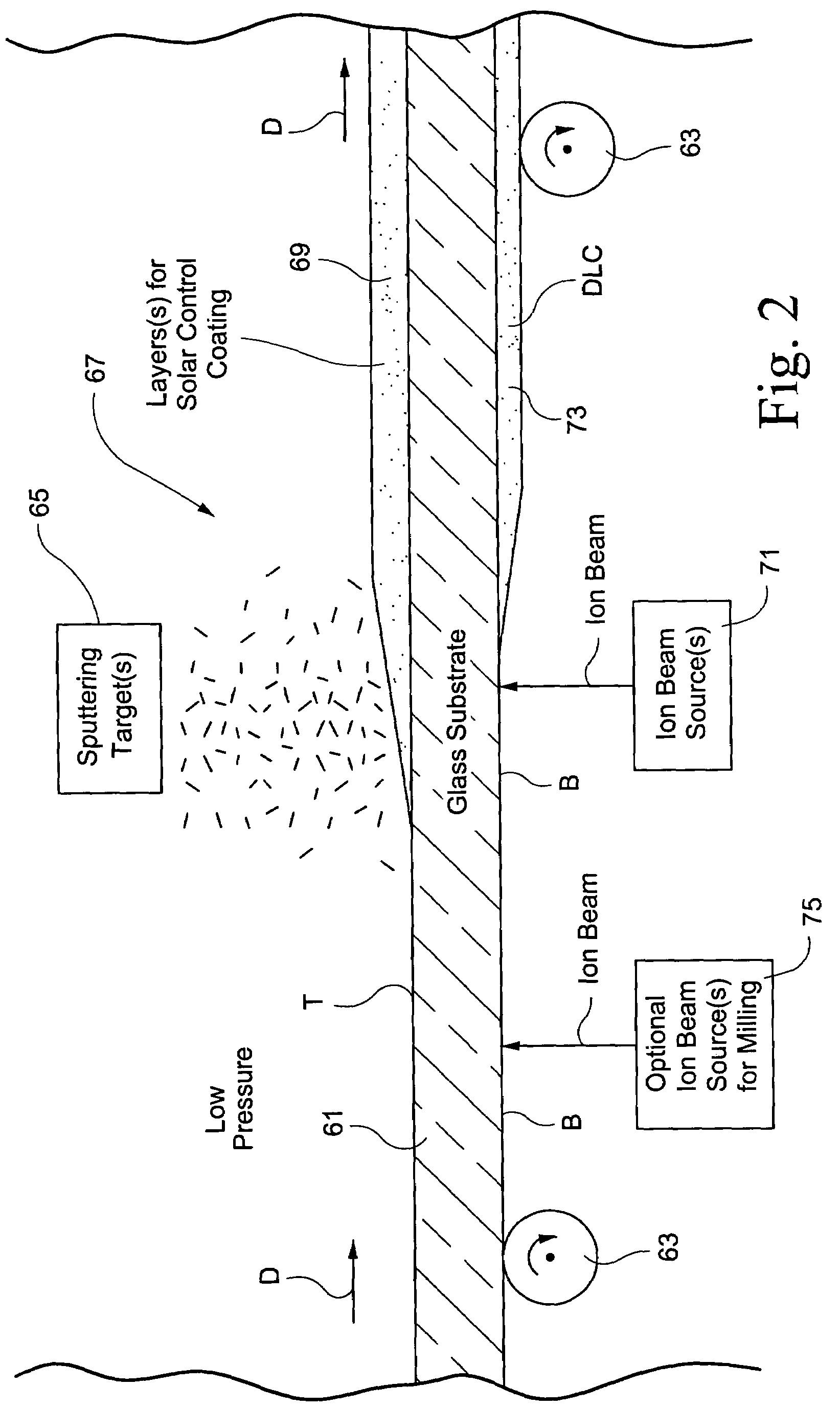
[0028]FIG. 2 is a perspective view of a coating apparatus according to an example embodiment of this invention. The coating apparatus may include one or more sputter coating chambers and at least one ion beam source used to mill and / or coat the substrate passing therethrough. In the FIG. 2 example, glass substrate 61 is shown passing through the coating apparatus in direction D. Substrate 61 may be conveyed through the coating apparatus by a plurality of rollers 63, or in any other suitable manner.

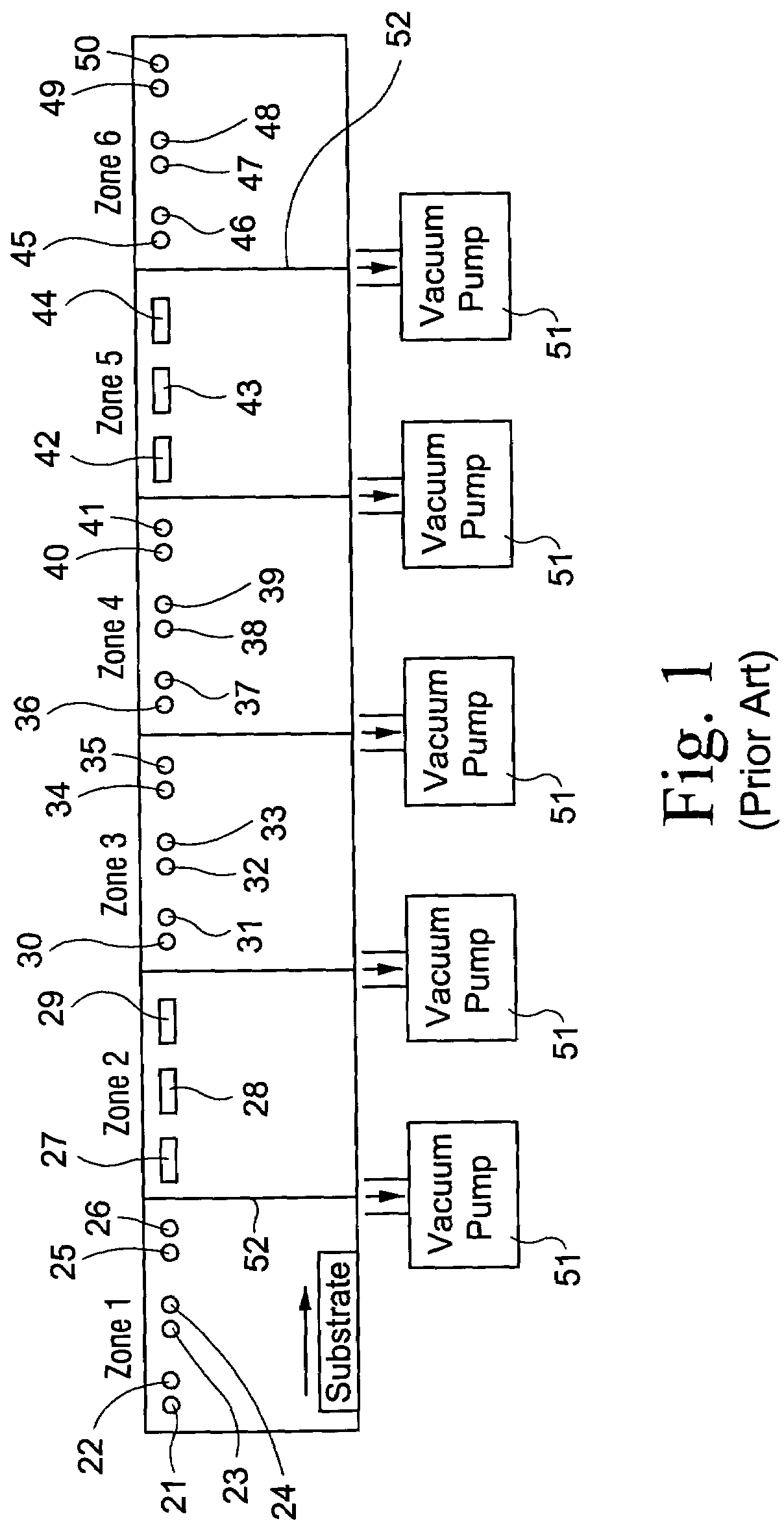
[0029]The coating apparatus includes at least one sputtering target(s) 65. The at least one sputtering target 65 may correspond, for example and without limitation, to one or more of sputtering targets 21–50 of FIG. 1. In the FIG. 2 example (and in FIG. 1), the sputtering target(s) 65 is provided at an elevation above the substrate 61 passing ...


PUM

PropertyMeasurementUnit
Pressureaaaaaaaaaa
Pressureaaaaaaaaaa
Dielectric polarization enthalpyaaaaaaaaaa

Abstract

A coating apparatus deposits a first coating (single or multi-layered) onto a first side of a substrate (e.g., glass substrate) passing through the apparatus, and a second coating (single or multi-layered) onto the other or second side of the substrate. In certain example embodiments, the first coating may be deposited via sputtering while the second coating is deposited via ion beam deposition. In such a manner, it is possible to coat both sides of the substrate in a single apparatus in an efficient manner. In other embodiments, the coating apparatus may sputter a coating onto a first side of the substrate and ion beam mill at least one surface of the substrate as the substrate passes through the coating apparatus. In other embodiments of this invention, a dual mode chamber may be provided that is adapted to receive a removable ion beam module on one side of a substrate and a removable sputtering module on the other side of the substrate. The different removable modules may or may not be used simultaneously in different embodiments of this invention.

Description

[0001]This application claims priority on Provisional U.S. Patent Application Nos. 60 / 377,620, filed May 6, 2002, and 60 / 431,192, filed Dec. 6, 2002, the disclosures of which are both hereby incorporated herein by reference in their entireties.[0002]This invention relates to an apparatus for coating a substrate (e.g., glass substrate) on both major surfaces / sides thereof. In particular, this invention relates to a method and corresponding apparatus for sputtering a coating onto a first side of the substrate and ion beam depositing another coating onto the other side of the substrate. In other embodiments, this invention relates to a coating apparatus which sputters a coating onto a first surface of a substrate passing therethrough and ion beam mills the first and / or second surface of the substrate in order to remove glass therefrom.BACKGROUND OF THE INVENTION[0003]Sputter coated glass articles are known in the art. For example, see U.S. Pat. Nos. 5,770,321, 5,298,048, and 5,403,458,...

Claims


Application Information

Patent Timeline
IPC IPC(8): C23C14/35C23C16/00C03C17/00C03C17/36C23C14/56C23C16/26
CPCC03C17/002C03C17/36C03C17/3618C03C17/3634C03C17/3644C03C17/366C23C14/562C23C16/26C03C2217/78
Inventor THOMSEN, SCOTT V.WALTON, HUGH A.
Owner GUARDIAN GLASS LLC
Why Eureka
Try Eureka