High PSRR, high accuracy, low power supply bandgap circuit

Active Publication Date: 2007-04-03
MONTEREY RES LLC
View PDF7 Cites 103 Cited by
  • Summary
  • Abstract
  • Description
  • Claims
  • Application Information

AI Technical Summary

Benefits of technology

[0027]In addition to improving the accuracy with which the reference current from the current generation circuit is copied to the output node of the Bandgap circuit, the second operational amplifier is advantageously configured for increasing the output impedances of the first and second NMOS cascode current sources. This may significantly reduce the portion of the power supply noise that may appear between the gate and source terminals of the upper PMOS transistor in the PMOS cascode current source. In other words, the sensitivity of the Bandgap reference circuit output current to power supply noise may be significantly decreased due to the inclusion of the second operational amplifier in the current replication stage.
[0028]The high impedance of the PMOS cascode current source output may also decrease the output node sensitivity to power supply noise. This advantage may be particularly apparent if large digital blocks, which generate significant switching noise, share the same power supply with sensiti

Problems solved by technology

Low power supply values preclude the use of cascoded devices in the current generation circuit due to voltage headroom limitations, thus increasing the power supply noise sensitivity of circuit 310 (and consequently, circuit 300).
However, this specification may be difficult to achieve at low power supply voltage values due to voltage headroom limitations.
Similar to circuit 310, the output of circuit 320 may also be affected by errors due to power supply, temperature and/or process variations, as well as curr

Method used


Image

  • High PSRR, high accuracy, low power supply bandgap circuit
  • High PSRR, high accuracy, low power supply bandgap circuit
  • High PSRR, high accuracy, low power supply bandgap circuit

Examples


Embodiment Construction

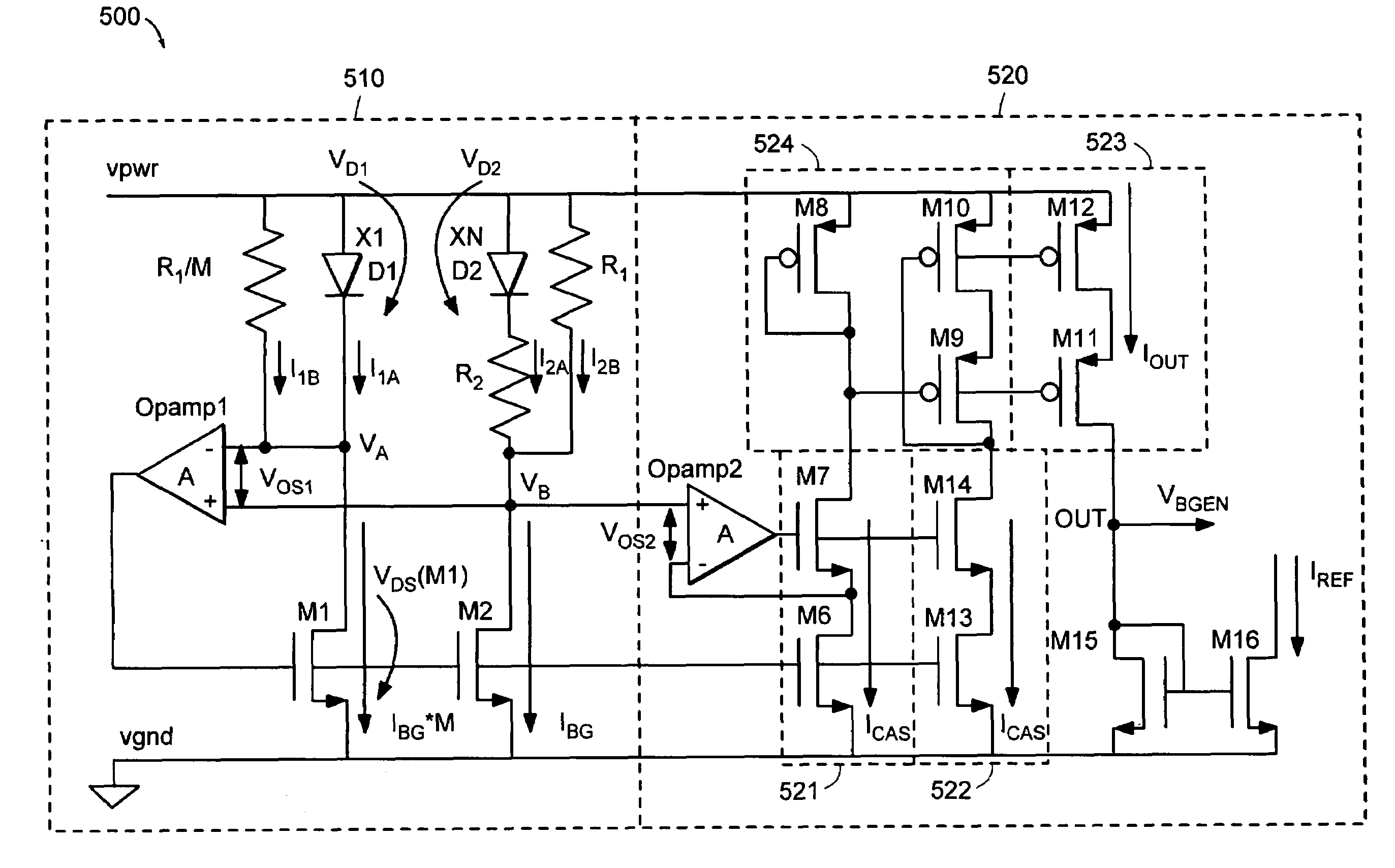
[0047]Turning to the drawings, an exemplary Current output Bandgap circuit 400 is illustrated in FIG. 4 as including a Bandgap Core 410 (referred to below as the “current generation circuit”) and a Current Mirroring stage 420 (referred to below as the “current replication circuit”). As shown in FIG. 4, the current generation circuit 410 is a modified diode bridge with two single PMOS voltage controlled current sources (M1 and M2) in two adjacent branches. The source terminals of PMOS current sources M1 and M2 are connected to the power supply node (vpwr) and their gate terminals are connected together. A third branch of the bridge, in series with the drain of PMOS transistor M1, is composed of a resistor (R1) in parallel with a p-n junction diode (D1). The third branch of the bridge is connected between node VA and ground node (vgnd) in FIG. 4. A fourth branch of the bridge, in series with the drain of PMOS transistor M2 and adjacent to the third branch, is composed of a p-n junctio...


PUM


Abstract

A bandgap circuit comprising a current generation circuit and a current replication circuit is provided herein. The output current of the current generation circuit is generated as a weighted sum of two currents. The circuit configuration of the current generation circuit allows it to function at low power supply voltages, e.g., on the order of 1 V. The current replication circuit includes an operational amplifier, which when configured in conjunction with MOS cascode current sources and the current generation circuit, significantly increases the accuracy and insensitivity to power supply noise of the bandgap circuit output current. A resistor may be included between the bandgap circuit output node and ground for generating a reference voltage with increased accuracy and insensitivity to power supply noise.

Description

PRIORITY CLAIM[0001]This application claims benefit of priority to the Provisional Patent Application Ser. No. 60 / 505,117, entitled “High PSRR, High Accuracy, Low Power Supply Bandgap Circuit,” filed Sep. 23, 2003, which is hereby incorporated in its entirety.BACKGROUND OF THE INVENTION[0002]1. Field of the Invention[0003]This invention relates to circuits used to generate reference currents and reference voltages on a semiconductor device and, more particularly, to low power supply voltage circuits capable of generating reference currents and reference voltages on a semiconductor device with high accuracy and reduced sensitivity to power supply noise.[0004]2. Description of the Related Art[0005]The following descriptions and examples are not admitted to be prior art by virtue of their inclusion within this section.[0006]Bandgap reference circuits are known for generating reference voltages, which exhibit little variation across defined ranges of temperatures, process corners and po...

Claims


Application Information

Patent Timeline
IPC IPC(8): G05F3/24G05F3/26
CPCG05F3/30
Inventor ZUPCAU, DAN LAURENTIUMEYERS, STEVEN
Owner MONTEREY RES LLC
Why Eureka
Try Eureka