
Measuring instrument provided with solid component concentrating means

a technology of concentrating means and measuring instruments, which is applied in the field of measuring instruments, can solve the problems of reducing the measured response current, affecting the accuracy of concentration measurement, and blood cell interference between the electrode and the electron transporter, so as to keep the measurement time short

Inactive Publication Date: 2007-04-10
ARKRAY INC
View PDF24 Cites 17 Cited by
  • Summary
  • Abstract
  • Description
  • Claims
  • Application Information

AI Technical Summary

Benefits of technology

[0006]It is an object of the present invention to control the effect of the solid component in the sample liquid and precisely measure concentration with a small amount of sample liquid while keeping the measurement time short.
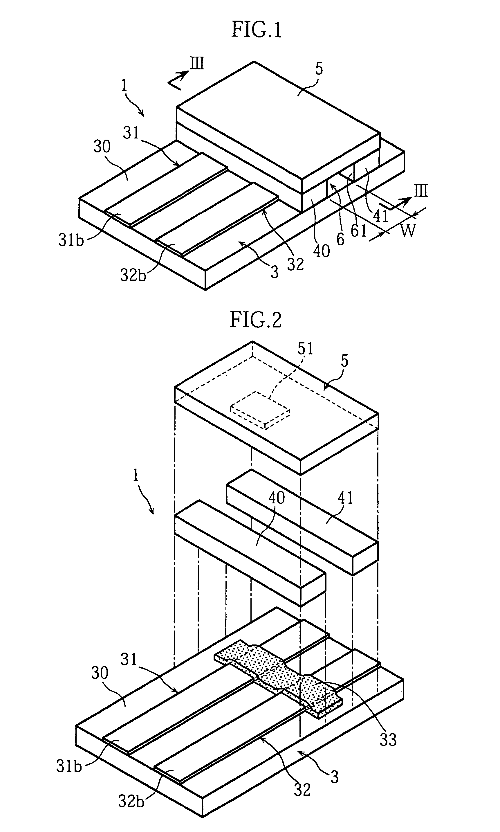
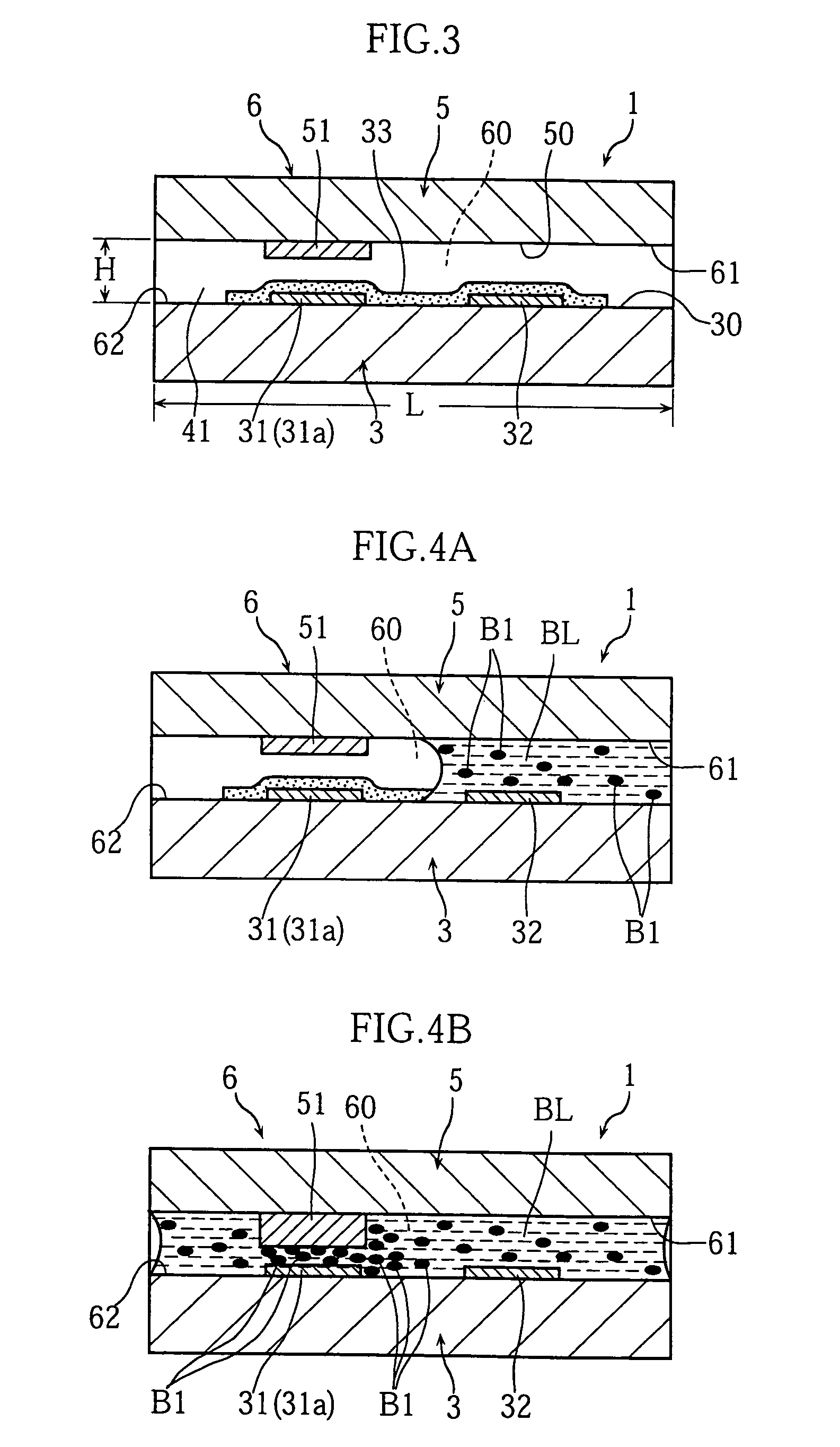
[0007]In the present invention a measuring instrument is provided which is an analytical instrument comprising a channel for moving a sample liquid containing a solid component and for providing a liquid reaction field and a first and second electrode which are used to apply voltage to the liquid reaction field, wherein the first electrode has an electron transfer interface for providing electrons to the liquid reaction field or receiving electrons from the reaction field when voltage is applied to the liquid reaction field via the first and second electrodes, and which is provided with concentration means for increasing the concentration of solid components in that part which contacts the electron transfer interface in the liquid reaction field.

Problems solved by technology

Consequently, the accuracy of concentration measurement is greatly affected by the accuracy of measurement of response current.
In such methods, when blood (blood containing blood cells) is used as a sample liquid, electron movement between the electrode and the electron transporter is impeded by blood cells present on the surface of the electrode.
As a result, the measured response current is reduced as the number of blood cells increases, producing measurement errors.
However, because in methods which filter blood cells in the measuring instrument the plasma component must pass through the separation membrane it takes a long time for the plasma to reach the surface of the electrode, prolonging the measurement time.
This problem can be solved by securing a large quantity of whole blood to be used, but this places a heavy burden of blood collection on the user.

Method used


Image

  • Measuring instrument provided with solid component concentrating means
  • Measuring instrument provided with solid component concentrating means
  • Measuring instrument provided with solid component concentrating means

Examples


example 1

(Preparation of Glucose Sensor)

[0072]In this example, a biosensor was formed with the same structure as in FIGS. 1 through 4. In this biosensor, the length L, width W and height H of internal channel 60 of capillary 6 were given as 3 mm, 1 mm and 40 μm, respectively (see FIGS. 1 and 3). Working electrode 31 and counter electrode 32 were formed by screen printing using carbon ink (Japan Acheson “Electrodag 423SS”). Reagent site 33 was given a two-layer structure consisting of an electron transport layer and an enzyme-containing layer. The electron transport layer was formed by first applying 0.4 μL of a first material liquid comprising an electron transporter to substrate 3, and then blow drying (30° C., 10% Rh) the first material liquid. The enzyme-containing layer was formed by first applying 0.3 μL of a second material liquid containing oxidoreductase to the electron transport layer, and then blow drying (30° C., 10% Rh) the second material liquid.

[0073]The first material liquid w...


PUM

PropertyMeasurementUnit
weight average grain sizeaaaaaaaaaa
thicknessaaaaaaaaaa
thicknessaaaaaaaaaa

Abstract

The present invention relates to a measuring instrument (1) comprising a channel (60) for moving a sample liquid (BL) containing a solid component (B1) and providing a liquid reaction field and first and second electrodes (31, 32) which are used to apply voltage to the liquid reaction field. The first electrode (31) has an electron transfer interface (31a) for transferring electrons between it and the liquid reaction field when voltage is applied to the liquid reaction field via the first and second electrodes (31, 32). The measuring instrument (1) comprises concentrating means (51) for increasing the concentration of solid components at portions thereof which contact the electron transfer interface (31a) in the liquid reaction field. The concentrating means (51) preferably comprises a water-absorbing layer containing an absorbent polymer material.

Description

TECHNICAL FIELD[0001]The present invention relates to a measuring instrument to be used for measuring the concentration of a specific component (such as glucose or cholesterol) in a sample liquid such as blood.BACKGROUND ART[0002]Some methods of measuring the concentration of a specific component in a sample liquid employ electrochemical techniques for example. In these methods, a reaction system is formed from a sample liquid, an oxidoreductase and an electron transporter for example, voltage is applied to this reaction system using electrodes, and the concentration of the specific component is computed based on the resulting response current. Such a reaction system is formed for example on a biosensor provided with a reagent part comprising an oxidoreductase and an electron transporter. Because an oxidation-reduction reaction occurs between the specific component and the electron transporter in the reaction system due to the catalytic effect of the oxidoreductase, the amount of th...

Claims


Application Information

Patent Timeline
Patent Type & Authority Patents(United States)
IPC IPC(8): G01N15/06G01N1/00C12Q1/00
CPCC12Q1/001C12Q1/005C12Q1/006G01N27/3272
Inventor YAMAOKA, HIDEAKIKATSUKI, KOJI
Owner ARKRAY INC
Learn More