Fixed mounted sorting cuvette with user replaceable nozzle

a technology of user-replaceable nozzles and sorting cuvettes, which is applied in the field of flow cytometry, can solve the problems of difficult to determine which elements require adjustment, the number of system limitations exist, and the alignment requires user time and considerable user expertis

Active Publication Date: 2007-04-10
BECTON DICKINSON & CO
View PDF26 Cites 110 Cited by
  • Summary
  • Abstract
  • Description
  • Claims
  • Application Information

AI Technical Summary

Benefits of technology

[0034]It is a further object that this system allows for efficient illumination and collection of light.

Problems solved by technology

However a number of limitations to the system exist.
Alignment requires user time and considerable user expertise.
At times it is difficult to determine which element requires adjustment.
Realignment necessitates both instrument down time and user time and expertise.
In addition, the need for constant realignment reduces the repeatability of system performance.
These references, while providing a method in which some of the issues relating to the alignment of the illumination optics are addressed, do not provide a method in which the flow cell and the light collection optics may also be fixed.
A number of different features in a common flow cytometer setup result in loss of illumination intensity or loss of intensity of collected light.
This requirement for increased power requires expensive and bulky liquid-cooled lasers that provide sufficient power to overcome losses and still allow sensitive target detection.
This refraction makes illumination less efficient and distorts light scatter.
Each dichroic mirror is not able to perfectly reflect or transmit a light beam.
As the beam is reflected or transmitted some light is lost.
The amount of collected fluorescence can be limited by the optical properties of the flow cell and the collection lens.
The high index of refraction during material transition results in the loss of collected light.
Vibration of the entire flow cell can result in alignment difficulty as well as additional light scatter created by the vibration.
In addition, if the optical analysis is performed in a stream-in-air, the drop-drive perturbations cause undulations on the free surface of the stream.
This causes a constant alteration of the light paths into and out of the jet of liquid, making measurement of scatter and focusing of the illumination beam more difficult.
This results in the formation of droplets.
One of the greatest losses of collected light occurs due to the transition between different materials that each have a different idex of refraction of light.
The light refraction between different materials (e.g. air and glass) may be significant and the resultant light refraction makes the collection and measurement of scattered or fluorescent light difficult.
A large degree of uncertainty in the nature of the stream of droplets is a common result of the way in which the nozzle is located to the flow channel.
However, there are a few problems inherent with this approach.
The first noted problem makes it difficult for a user to duplicate the mounting of the nozzle to a previous mounting configuration.
The second and third noted problems make it impossible.
If these procedures become even slightly out of coordination, the incorrect droplets could be charged for sorting or the system could fail to collect the desired particles or cells.
Sorting using a system in which analysis is done in a channel also presents challenges.
This can make sorting particles optically analyzed in a cuvette channel more difficult.
Since prediction of the position of the particle depends on knowing the velocity of the particle, sorting particles becomes much more difficult if the velocity of the particle changes.

Method used


Image

  • Fixed mounted sorting cuvette with user replaceable nozzle
  • Fixed mounted sorting cuvette with user replaceable nozzle
  • Fixed mounted sorting cuvette with user replaceable nozzle

Examples


Embodiment Construction

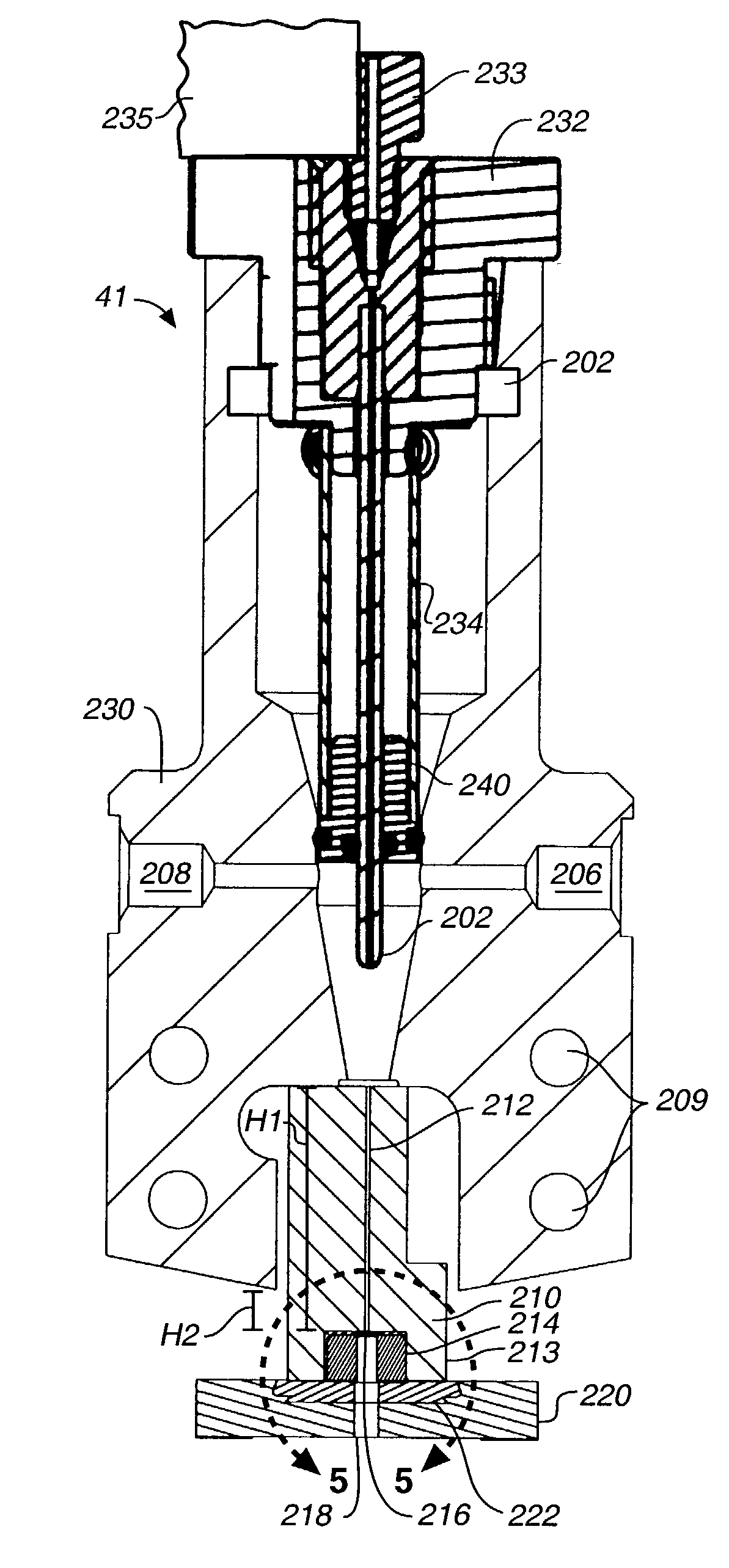
[0068]In the present invention, significant advantage is derived from a configuration in which a number of the optical elements may be fixed with respect to the flow cell. This advantage arises from the extent of directional stability afforded by the nozzle, which the user may remove and replace and which is self-aligning. The nozzle is insertable in the flow cuvette at a location where the nozzle is registered in place. This registration allows the nozzle to be inserted and positioned such that the nozzle is constrained both as to translation and rotation. Because only the nozzle is movable, the flow cell may be fixed, and does not need to be positioned on a stage that may be angularly or directionally repositioned. As a result, no removal or replacement of the flow cell is required and the user will not have to adjust or realign the flow cell assembly to align the stream of droplets with a required direction for sorting.

[0069]Because the flow cell and flow channel never need to be...


PUM

PropertyMeasurementUnit
lengthaaaaaaaaaa
lengthaaaaaaaaaa
sizeaaaaaaaaaa

Abstract

A flow cell and flow cytometer in which a nozzle at the end of a flow channel is disposed on a removable substrate held at a registered location on a flow cell. Other elements including illumination optics, light collection optics, and the flow cell may then be positioned at fixed locations and would not require subsequent periodic adjustment. The registered location for positioning the nozzle allows removal and replacement of the nozzle key with the nozzle subsequently positioned in the identical location.

Description

TECHNICAL FIELD[0001]The present invention relates to flow cytometry.BACKGROUND OF THE INVENTION[0002]Flow analysis has proven to be an important technology for the analysis of discrete targets. The applications of this technology include cellular assay to investigate a variety of cellular features including DNA content, specific nucleic acid sequences, chromatic structure, RNA content, specific antigens, surface receptors, cell morphology, DNA degredation and other assay targets. The targets of a flow cytometer may be multicellular organisms (e.g. microfilaria), cellular aggregates, viable cells, dead cells, cell fragments, organelles, large molecules (e.g. DNA), particles such as beads, viral particles or other discrete targets of this size range. The term “cells”, as used throughout, is used to refer to such discrete targets. This technology has a number of different applications, including diagnostic, clinical and research applications.[0003]Flow cytometry measures targets flowi...

Claims


Application Information

Patent Timeline
Patent Type & Authority Patents(United States)
IPC IPC(8): G01N33/00G01N21/64G01N15/14G01N21/05G01N21/78G01N33/483
CPCG01N15/14G01N15/1404Y10T436/117497Y10T436/101666Y10T436/119163
Inventor NORTON, PIERCE O.VRANE, DAVID R.JAVADI, SHERVIN
Owner BECTON DICKINSON & CO
Why Eureka
Try Eureka