Dynamic logic circuit apparatus and method for reducing leakage power consumption via separate clock and output stage control

a logic circuit and power consumption technology, applied in logic circuits, power consumption reduction, pulse techniques, etc., can solve the problems of dynamic circuits in non-functional power-saving mode, increasing portion of power consumption of such circuits, and reducing the efficiency of dynamic circuits, so as to reduce leakage power consumption, reduce leakage, and fast evaluate time

Inactive Publication Date: 2007-04-10
INT BUSINESS MASCH CORP
View PDF13 Cites 11 Cited by
  • Summary
  • Abstract
  • Description
  • Claims
  • Application Information

AI Technical Summary

Benefits of technology

[0011]The apparatus is a dynamic logic circuit and the method is a method of operation of the dynamic logic circuit that reduce leakage power consumption via separate clock and output stage control of the dynamic circuit. A power control signal turns on the output inverter foot device after the dynamic node has had sufficient time to evaluate, providing a fast evaluate time and reducing leakage through the inverter input when the foot device is off. The foot device is turned on after a predetermined time period has elapsed after the precharge signal is deasserted and then turned off after a second predetermined time period has elapsed after the precharge signal is asserted. Alternatively, a coarsely timed static power control signal may be used to control the inverter foot devices separate from the precharge control. A delay may be used to provide the power control signal, and may be selectively bypassed to remove any maximum frequency penalty associated with the power savings mode. Alternatively, a static power control signal may be used for coarse power savings mode control.
[0012]The drains of the inverter foot devices can be commonly connected across multiple circuits, reducing the foot device total area.
[0013]A special keeper circuit may be employed to hold a precharge state value at the inverter output when the foot devices are disabled. The keeper circuit uses substantially lower current level than the inverter transistors, providing a low-leakage mechanism for retaining the inverter output state in the low power mode.

Problems solved by technology

As the operating voltage of dynamic circuits is decreased, an increasing portion of the power consumption of such circuits is now determined by leakage in and through the output stages of the individual logic circuits.
Gate tunneling causes some leakage current to occur through the N-channel device to the low voltage power supply rail.
While it is possible to supply foot devices throughout the dynamic circuit for power control, doing so disables all of the outputs of the individual gates, causing the dynamic circuit to be in a non-functional power-saving mode.
As such, only a very “coarse” control of leakage power consumption can be achieved, as outputs feeding a next logic stage are invalidated and if the evaluation node is also isolated by a disabled footer, the state held at that node is likewise invalidated.

Method used


Image

  • Dynamic logic circuit apparatus and method for reducing leakage power consumption via separate clock and output stage control
  • Dynamic logic circuit apparatus and method for reducing leakage power consumption via separate clock and output stage control
  • Dynamic logic circuit apparatus and method for reducing leakage power consumption via separate clock and output stage control

Examples


Embodiment Construction

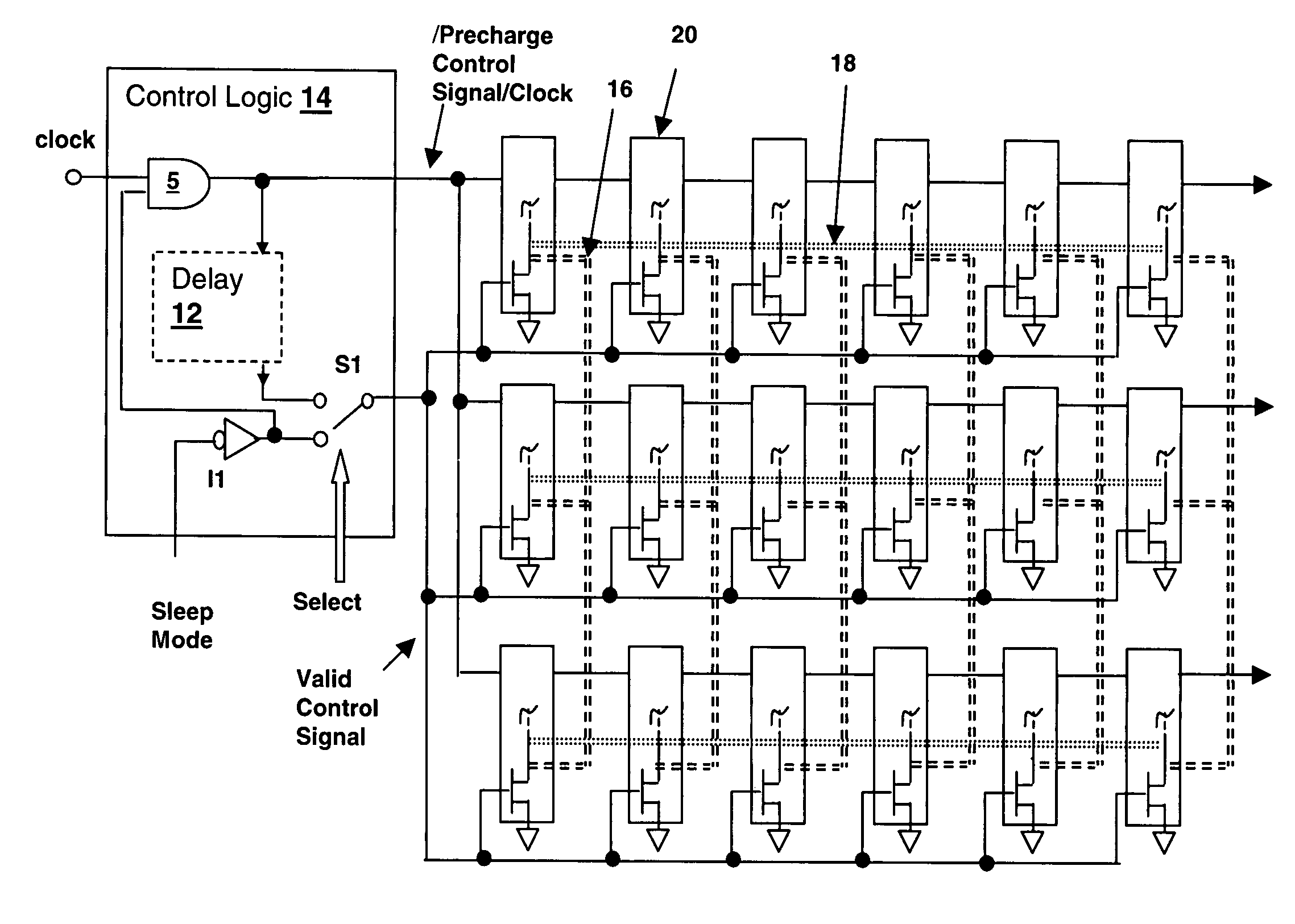
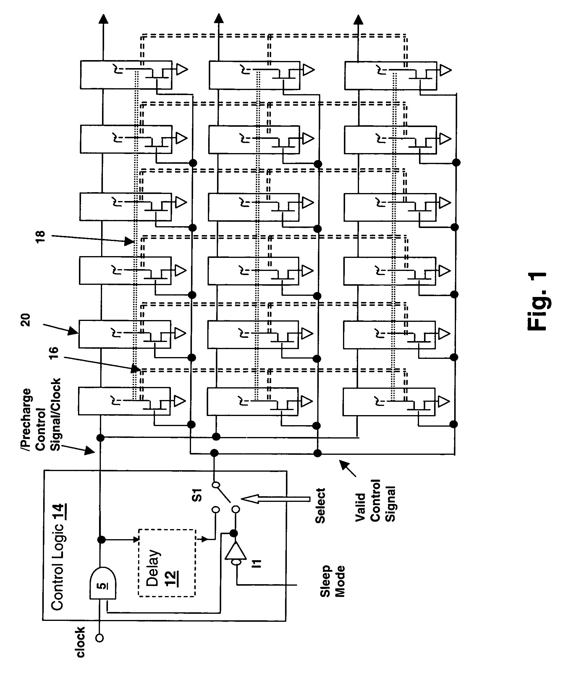
[0019]With reference now to the figures, and in particular with reference to FIG. 1, there is depicted a schematic diagram of an arrangement of dynamic logic circuits embodying a method and an apparatus in accordance with the present invention.

[0020]Dynamic logic gates 20 are arranged in horizontal rows and vertical columns in the figure, with horizontal rows representing cascaded stages of dynamic logic that provide sequential combinatorial evaluation of outputs of the previous stage along with optional feedback from the same or successive stages. While the illustration does not show the logical inputs and outputs of dynamic logic gates 20, it should be understood that such connections are employed. For example, an accumulator may provide an exclusive-OR implementing a full adder summing the stage inputs with the stages outputs, a multiplier-accumulator may employ a shift function (vertical) in conjunction with an adder, et cetera.

[0021]Each of dynamic logic gates 20 receives two c...


PUM


Abstract

A dynamic logic circuit apparatus and method for reducing leakage power consumption via separate clock and output stage control reduces power consumption of processors and other systems incorporating dynamic circuits. The power control signal may be a delayed version of the logic clock and turns on the output inverter foot device after the dynamic node has had sufficient time to evaluate, providing a fast evaluate time and reducing leakage through the inverter input when the foot device is off. Alternatively, a coarsely timed static power control signal may be used to control the inverter foot devices. The drains of the inverter foot devices can be commonly connected across multiple circuits, reducing the foot device total area.

Description

[0001]This invention was made with Government support under NBCH30390004, BGR W0132280 awarded by PERCS II. THE GOVERNMENT HAS CERTAIN RIGHTS IN THIS INVENTION.CROSS-REFERENCE TO RELATED APPLICATIONS[0002]This application is related to co-pending U.S. patent application Ser. No. 10 / 992,486, filed concurrently with this application and entitled “DYNAMIC LOGIC CIRCUIT INCORPORATING REDUCED LEAKAGE STATE-RETAINING DEVICES”, by the same inventors and assigned to the same assignee. The specification of the above-referenced application is hereby incorporated by reference. This application is also related to U.S. patent application Ser. No. 10 / 965,106 filed on Oct. 14, 2004, now U.S. Pat. No. 7,088,141 and entitled “MULTI-THRESHOLD COMPLEMENTARY METAL-OXIDE SEMICONDUCTOR (MTCMOS) BUS CIRCUIT AND METHOD FOR REDUCING BUS POWER CONSUMPTION VIA PULSED STANDBY SWITCHING”, having at least one common inventor and assigned to the same assignee.BACKGROUND OF THE INVENTION[0003]1. Technical Field[00...

Claims


Application Information

Patent Timeline
Patent Type & Authority Patents(United States)
IPC IPC(8): H03K19/096
CPCH03K19/0016H03K19/0966
Inventor NGO, HUNG CAIKUANG, JENTE BENEDICTDEOGUN, HARMANDER SINGHKLEINOSOWSKI, AJ
Owner INT BUSINESS MASCH CORP
Why Eureka
Try Eureka