Semiconductor device and fabrication method for the same

a technology of semiconductors and semiconductors, applied in the field of semiconductor devices, can solve the problems of avoiding conventional techniques, failing to align components in desired positions, and avoiding alignment of components, and achieve the effect of high reliability and accurate alignmen

Inactive Publication Date: 2007-04-17
SHARP KK
View PDF19 Cites 234 Cited by
  • Summary
  • Abstract
  • Description
  • Claims
  • Application Information

AI Technical Summary

Benefits of technology

[0017]By thus detecting the position of the marker, alignment of the components in accordance with the transferred layer may be securely performed. Namely, the alignment may be accurately and properly performed in accordance with the marker.
[0018]Therefore, in the semiconductor device fabrication step, the fabrication of the metal leads etc. after the transfer step may be performed with accurate and secure alignment. On this account, the misalignment of the metal leads etc. may be securely prevented, thereby realizing a highly-reliable semiconductor device.
[0019]Further, for example, the marker may be used for alignment on mounting the semiconductor device of the present invention to other substrate (e.g. an active matrix substrate of a liquid crystal display device), that allows secure mounting thereof with accurate alignment.
[0021]With the foregoing arrangement, alignment of the components in accordance with the transferred layer in the fabrication steps after the bonding step may be securely performed in accordance with the detection result of the marker. Namely, the alignment may be accurately and properly performed in accordance with the marker. On this account, the misalignment of the metal leads etc. may be securely prevented, thereby realizing a highly-reliable semiconductor device.

Problems solved by technology

The need for better performance arises from the insufficient performance of the transistor for making a high-performance Si device, owning to the fact that the mobility is decreased or S coefficient (sub-threshold coefficient) is increased by the presence of a local level in the gap caused by the incomplete crystallinity of the polycrystalline Si, or by the presence of a defect or such a gap local level in the vicinity of a crystal grain boundary.
However, the foregoing conventional techniques of Japanese Patents No. 2743391 and No. 3141486 suffer from some difficulties in aligning components (for example, gate electrode etc. of the semiconductor device) in accordance with semiconductor device, after the substrate containing the semiconductor device is transferred to the base substrate.
More specifically, after the substrate having the semiconductor is transferred, the peripheral components should be aligned in accordance with the position of the semiconductor device; however, since the semiconductor substrate is not transparent, the components (gate electrode etc.) under the transferred substrate cannot be seen, thus failing to align them in desired positions.

Method used


Image

  • Semiconductor device and fabrication method for the same
  • Semiconductor device and fabrication method for the same
  • Semiconductor device and fabrication method for the same

Examples


first embodiment

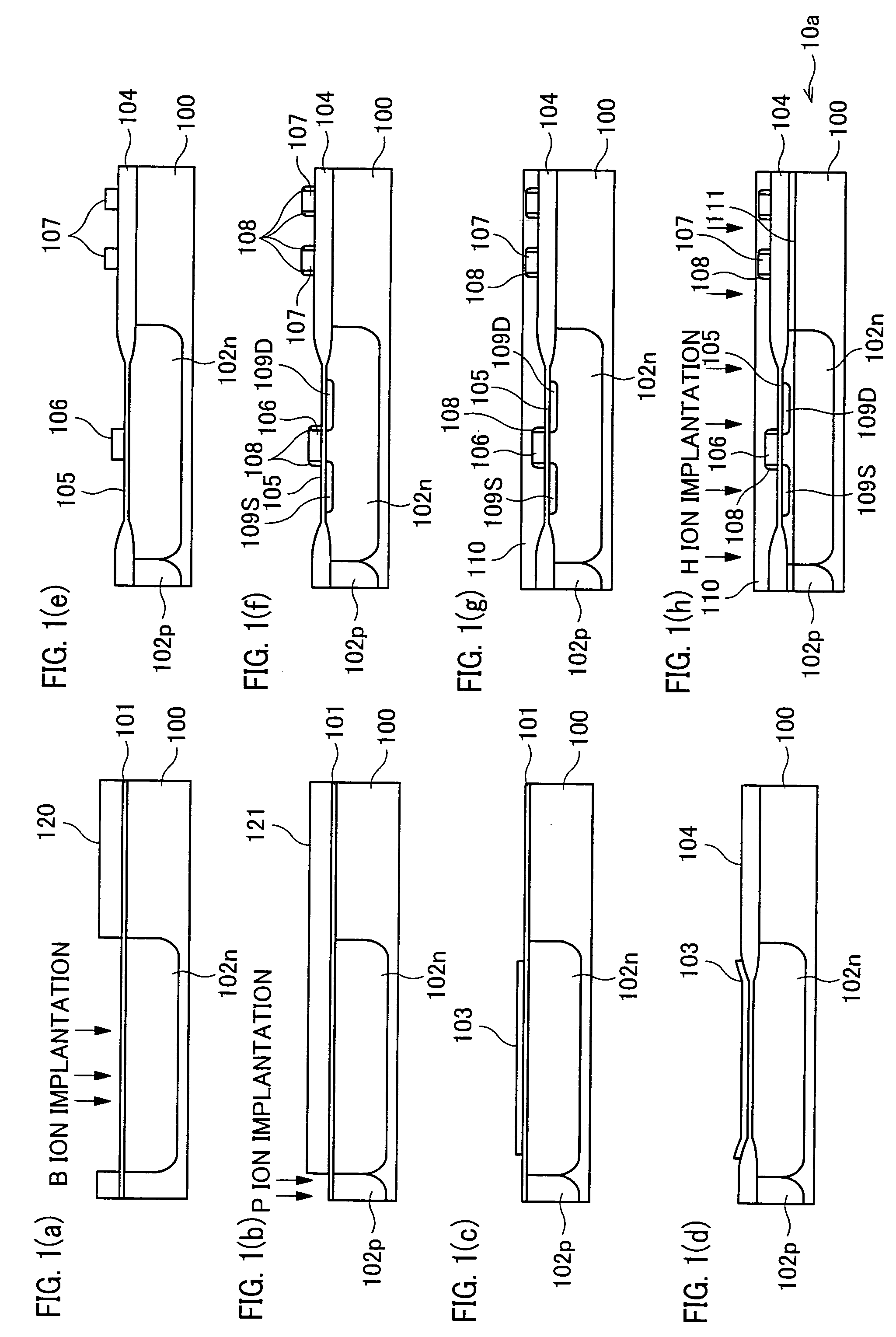
[0030][First Embodiment]

[0031]One embodiment of the present invention is described below with reference to Figures.

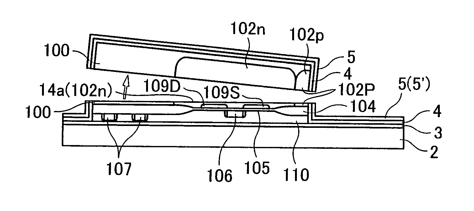
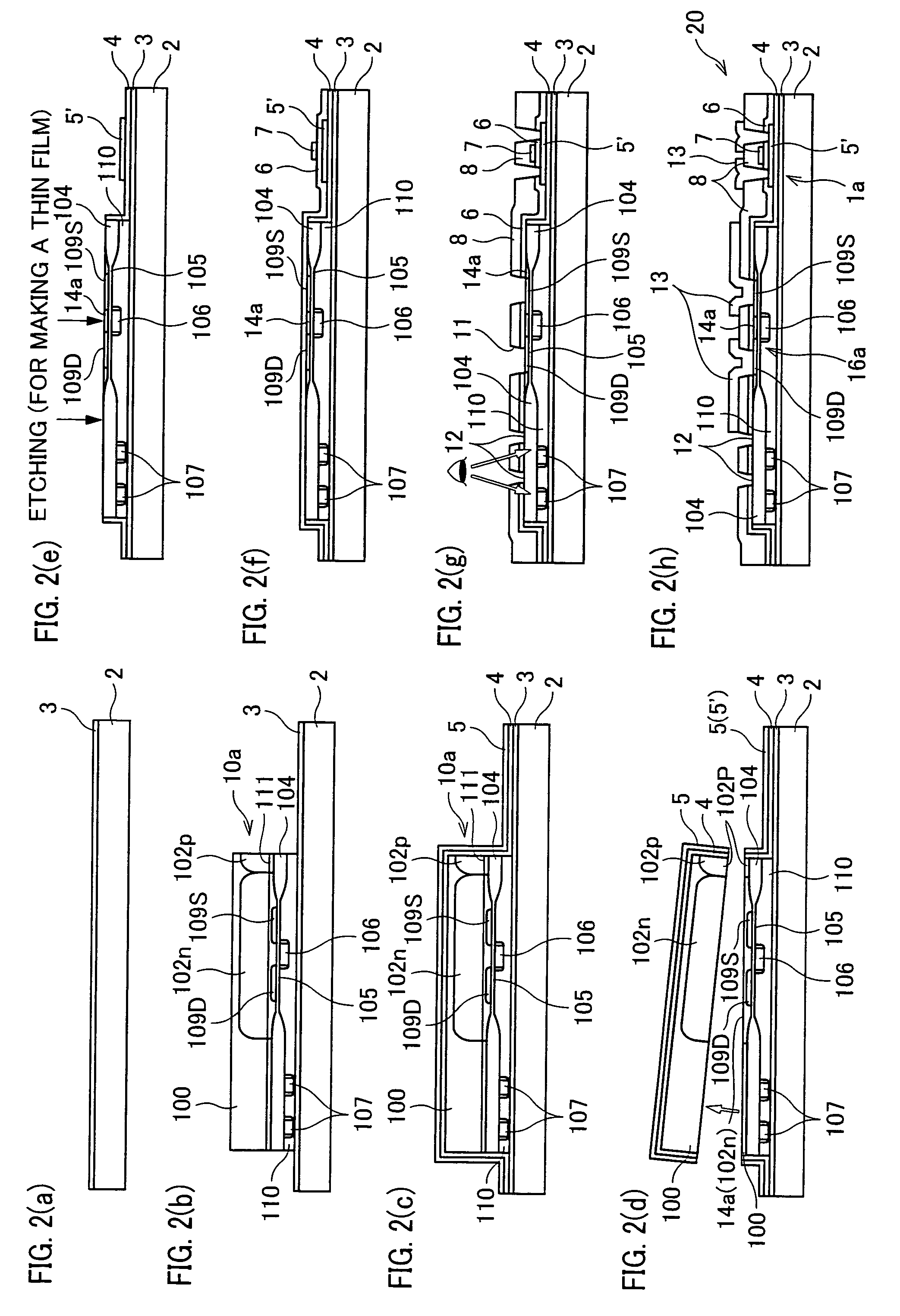
[0032]As described herein, a semiconductor device 20 of the present embodiment provides improved performance and improved functionality by forming a MOS (Metal Oxide Semiconductor) non-monocrystalline Si thin film transistor (deposited device, second device) and a MOS monocrystalline Si thin film transistor (transferred device, first device) in different regions on an insulating substrate. As described in this embodiment, the semiconductor device 20 is formed on an active-matrix substrate using TFT.

[0033]The MOS thin film transistor is a common transistor including an active semiconductor layer, a gate electrode, a gate insulating film, and dense impurity doped regions (source electrodes and drain electrodes) formed on the both sides of a gate, wherein the gate electrode adjusts the carrier density of the semiconductor layer beneath the gate, so as to adjust a flow of s...

second embodiment

[0099][Second Embodiment]

[0100]Another embodiment of the present invention is explained below with reference to the figures.

[0101]In the first embodiment above, the element isolation was realized by Locos Oxidization (field oxide film (SiO2 film) 104); however, there are some alternatives. For example, element isolation may be realized by shallow trench isolation (trench isolation), in which the alignment mark is formed on the filled hole of the trench section.

[0102]The present embodiment explains a semiconductor device and a fabrication method thereof, in which the element isolation of the monocrystalline Si substrate is realized by trench isolation.

[0103]The present embodiment uses a semiconductor device 20b that is the same as the semiconductor device 20 above, except for a monocrystalline Si substrate 10b having different structure of the element-isolation region from that of the monocrystalline Si substrate 10a. For ease of explanation, materials having the equivalent functions...

third embodiment

[0146][Third Embodiment]

[0147]Still another embodiment of the present invention is explained below with reference to the figures. FIGS. 5(a) through 5(k) are cross-sectional views illustrating manufacturing steps according to the present embodiment in which a monocrystalline Si substrate 10c is transferred on the insulating substrate 2. FIGS. 6(a) through 6(h) are cross-sectional views illustrating other manufacturing steps of a semiconductor device according to the present embodiment.

[0148]In the first and second embodiments, the alignment mark 107 is formed from a polysilicon, which is also used for the gate electrode 106. However, any material allowing detection by light may be used.

[0149]The present embodiment explains a semiconductor device including an alignment mark 114 formed from the same metal material as that used for metal leads 113 formed on the monocrystalline Si substrate 10c, and also explains the manufacturing method thereof.

[0150]The present embodiment uses a semic...


PUM

PropertyMeasurementUnit
thicknessaaaaaaaaaa
thicknessaaaaaaaaaa
resistivityaaaaaaaaaa

Abstract

In a semiconductor device including a monocrystalline thin film transistor 16a that has been formed on a monocrystalline Si wafer 100 and then is transferred to a insulating substrate 2, LOCOS oxidization is performed with respect to the element-isolation region of the monocrystalline Si wafer 100 so as to create a field oxide film (SiO2 film) 104, and a marker 107 is formed on the field oxide film 104. With this structure, alignment of components may be performed based on a gate electrode 106 upon or after the transfer step.

Description

[0001]This Nonprovisional application claims priority under 35 U.S.C. § 119(a) on Patent Application No. 2003 / 361734 filed in Japan on Oct. 22, 2003, No. 2004 / 212230 filed in Japan on Jul. 20, 2004 and the entire contents of which are hereby incorporated by reference.FIELD OF THE INVENTION[0002]The present invention relates to a semiconductor device with plural kinds of transistors of different characteristics formed on a single substrate, and also relates to a fabrication method of such a semiconductor device.BACKGROUND OF THE INVENTION[0003]An active-matrix display device, one of conventional display devices, carries out driving of a display panel, such as a liquid crystal display panel, or an organic EL display panel, by a thin film transistor (“TFT” hereinafter), that is made of an amorphous silicon (amorphous Si; “a-Si” hereinafter) or a polycrystalline silicon (polycrystalline Si; “p-Si” hereinafter) and is formed on a glass substrate.[0004]Particularly common is one with inte...

Claims


Application Information

Patent Timeline
Patent Type & Authority Patents(United States)
IPC IPC(8): H01L21/76G02F1/1368H01L21/02H01L21/336H01L21/58H01L21/60H01L21/68H01L21/762H01L21/77H01L21/822H01L21/84H01L23/544H01L27/06H01L27/12H01L29/423H01L29/786
CPCH01L21/6835H01L23/544H01L24/24H01L24/26H01L24/82H01L24/83H01L27/1203H01L27/1214H01L27/1266H01L29/78654H01L2924/1305H01L2924/13091H01L2924/01019H01L2221/68359H01L2221/68363H01L2223/54473H01L2224/24226H01L2224/8385H01L2224/83894H01L2924/01005H01L2924/01013H01L2924/01015H01L2924/01027H01L2924/01033H01L2924/01051H01L2924/01057H01L2924/01082H01L2924/01088H01L2924/04941H01L2924/07802H01L2924/14H01L2924/19041H01L2924/01006H01L2924/00H01L2223/54426H01L2924/12042
Inventor OGAWA, YASUYUKITAKAFUJI, YUTAKA
Owner SHARP KK
Why Eureka
Try Eureka