Method for forming metal oxide film and method for forming secondary electron emission film in gas discharge tube

a technology of metal oxide film and gas discharge tube, which is applied in the manufacture of electric discharge tube/lamp, discharge tube coating, electrode system, etc., can solve the problems of increasing the significance of the problem and the uneven thickness of the metal oxide film

Inactive Publication Date: 2007-04-24
SHINODA PLASMA
View PDF17 Cites 11 Cited by
  • Summary
  • Abstract
  • Description
  • Claims
  • Application Information

AI Technical Summary

Benefits of technology

[0011]wherein the glass tube is an elongated glass

Problems solved by technology

The metal oxide film formed in the method as described above, however, has a problem that the thickness of the metal oxid

Method used


Image

  • Method for forming metal oxide film and method for forming secondary electron emission film in gas discharge tube
  • Method for forming metal oxide film and method for forming secondary electron emission film in gas discharge tube
  • Method for forming metal oxide film and method for forming secondary electron emission film in gas discharge tube

Examples


example 1

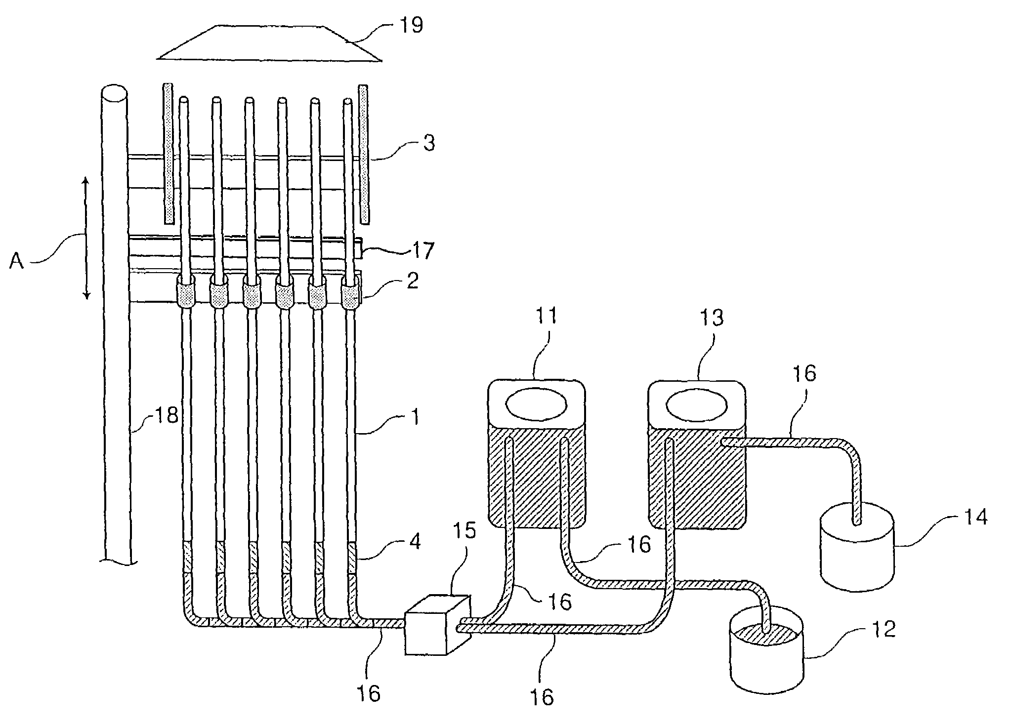
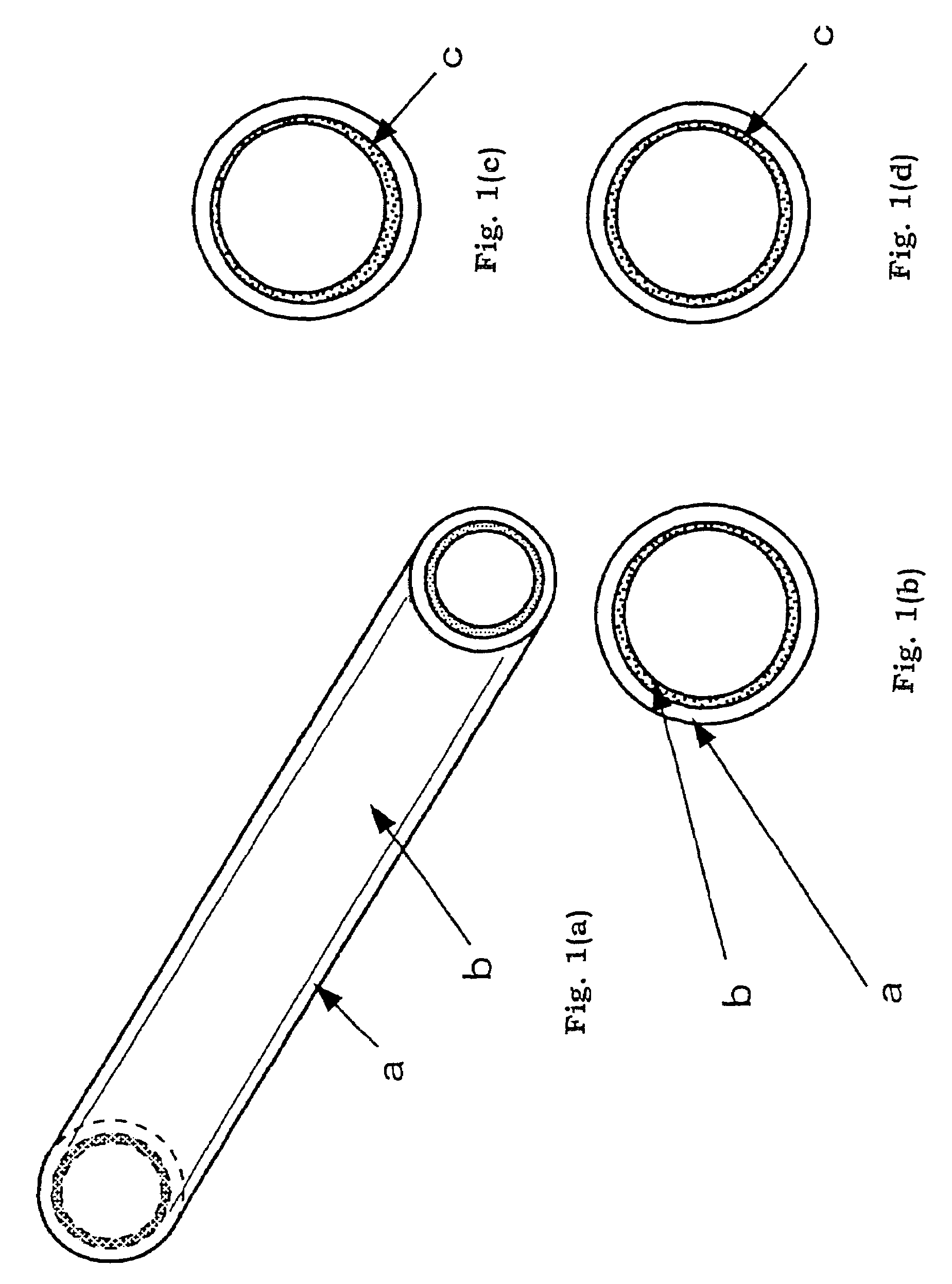
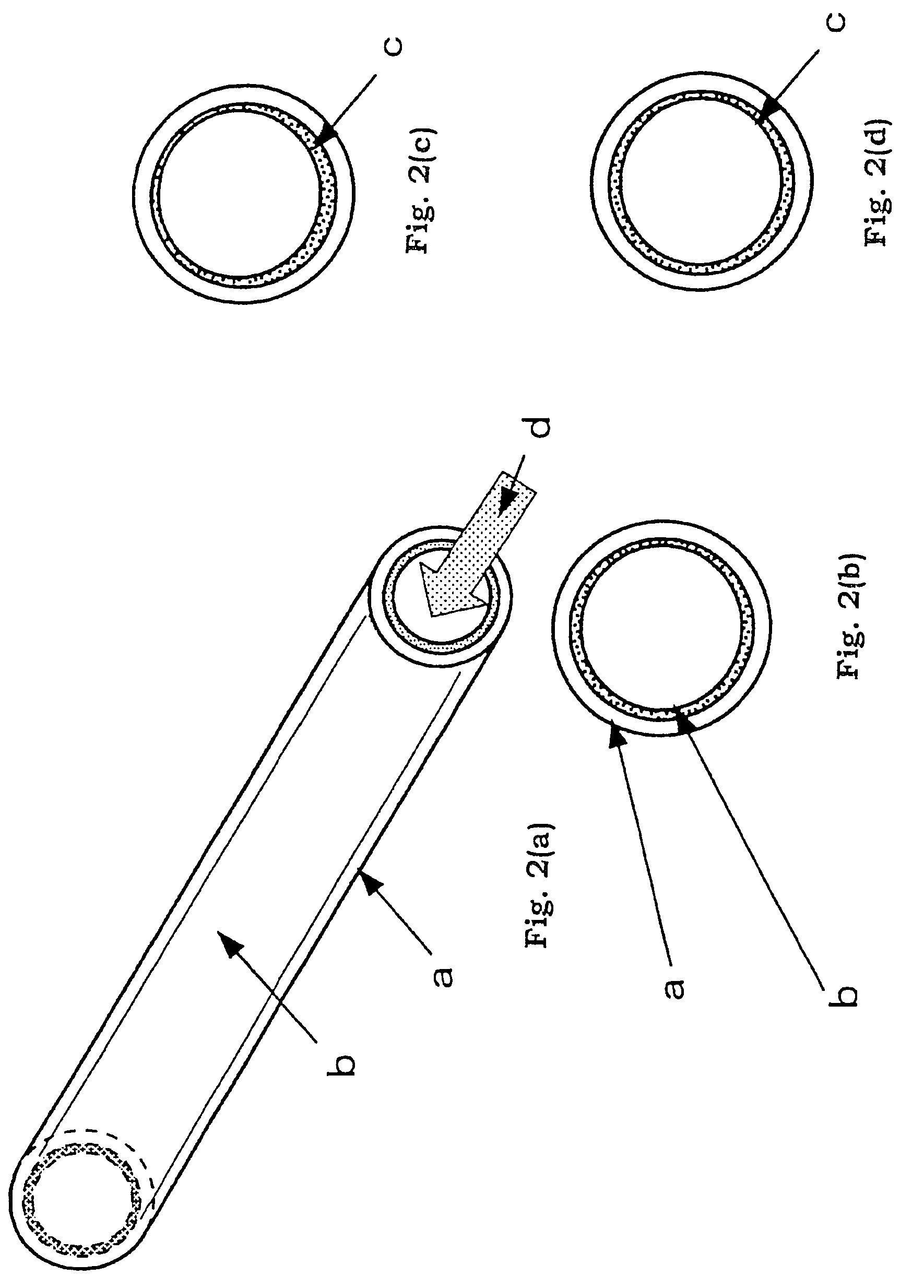
[0066]A coating solution comprising 1 part by weight of magnesium caproate, 1 part by weight of ethanol and 1 part by weight of propylene glycol monomethyl ether acetate (viscosity: 20 to 30 cps) was applied on the inner wall of a glass slender tube having an inner diameter of 0.8 mm and a length of 250 mm forming a tubular container of a gas discharge tube and the coating solution was dried, thereby forming a coating film. Specifically, the coating process was executed by introducing the coating solution into the end part of the slender tube, and disposing the slender tube in the spinner, and performing spin coating around the end part. Drying process was executed by heating for 15 minutes at 70° C. The thickness of the coating film was about 25,000 Å.

[0067]Next, both the front and back surfaces of the slender tube on which coating film was formed was irradiated with an ultraviolet ray having a wavelength of 254 nm from the low pressure mercury lamp for 10 minutes. After irradiatio...

example 2

[0069]A coating solution comprising 1 part by weight of magnesium caproate, 0.5 part by weight of ethanol and 0.4 part by weight of diethylene glycol monopropyl ether acetate (viscosity: 350 to 400 cps) was applied on the inner wall of a glass tube having an inner diameter of 0.8 mm and a length of 1,000 mm and the coating solution was dried, thereby forming a coating film. Specifically, the coating process was executed by introducing the coating solution into a lower opening of a slender tube which is held upright so that the interior of the slender tube is filled with the coating solution, and then slowly discharging the coating solution. Drying process was executed in discharging the coating solution, by means of a local heater which scans the coating solution adhering on the tube wall in the vicinity of the top face of the coating solution filling the slender tube, in accordance with the movement of the top face of the coating solution filling the slender tube. The thickness of ...


PUM

PropertyMeasurementUnit
Diameteraaaaaaaaaa
Diameteraaaaaaaaaa
Sizeaaaaaaaaaa

Abstract

According to the present invention, there is provided a method for forming a metal oxide film comprising, when a metal oxide film is formed by conducting a thermal treatment on a coating film containing an organic metal compound formed on an inner wall of a tube, performing an ultraviolet irradiation treatment or an ozone treatment on the coating film prior to or simultaneously with the thermal treatment.

Description

CROSS-REFERENCE TO RELATED APPLICATION[0001]This application is related to Japanese application No. 2002-238403 filed on Aug. 19, 2002, whose priority is claimed under 35 USC § 119, the disclosure of which is incorporated by reference in its entirety.BACKGROUND OF THE INVENTION[0002]1. Field of the Invention[0003]The present invention relates to a method for forming a metal oxide film and a method for forming a secondary electron emission film in a gas discharge tube. More specifically, the present invention relates to a method for forming a metal oxide film on an inner wall of a tube.[0004]2. Description of the Related Arts[0005]A variety of methods for forming a metal oxide film on an inner wall of a tube have been conventionally known, and among these, for example, a method which comprises applying a coating solution containing an organic metal compound on the inner wall of the tube to form a coating film, and performing thermal treatment on the coating film, thereby forming the ...

Claims


Application Information

Patent Timeline
IPC IPC(8): B05D7/22B05D3/02B05D3/06B05D3/10B05D5/12H01J9/02C03C17/25C23C18/06C23C18/12C23C18/14H01J1/70H01J9/20H01J11/18H01J11/22H01J11/34H01J11/40
CPCC03C17/25C23C18/06C23C18/12C23C18/1216C23C18/1279C23C18/14H01J1/70H01J9/20H01J11/18H01J2209/012C03C2217/228C03C2218/113C03C2218/32H01J61/35C03C2217/21C23C18/143B05D3/06
Inventor YAMADA, HITOSHITOKAI, AKIRAISHIMOTO, MANABUNAKAZAWA, AKIRAAWAMOTO, KENJISHINODA, TSUTAE
Owner SHINODA PLASMA
Why Eureka
Try Eureka