White light emitting device and method of making same

a light-emitting diode and white light-emitting technology, which is applied in the direction of semiconductor devices, basic electric elements, electrical equipment, etc., can solve the problems of uv radiation from the leds, the combined color would change noticeably, and the life of the uv leds is relatively shor

Active Publication Date: 2007-04-24
OPTRONIC SCI LLC
View PDF13 Cites 7 Cited by
  • Summary
  • Abstract
  • Description
  • Claims
  • Application Information

AI Technical Summary

Benefits of technology

[0016]Thus, the first aspect of the present invention provides a method of producing a white-light emitting source, the white light comprising at least a first color component with a first wavelength, a second color component with a second wavelength, and a third color component with a third wavelength, the first wavelength shorter than the second wavelength, the second wavelength shorter than the third wavelength. The method comprises the steps of:
[0014]Thus, it is advantageous and desirable to provide a method to produce a semiconductor light source containing wavelength components in RGB.

Problems solved by technology

(1) Putting discrete red, green and blue LEDs in a “lamp” and use various optical components to mix light in red, green and blue colors emitted by those discrete LEDs. However, because of the different operating voltages for LEDs of different colors, multiple control circuits are required. Furthermore, the lifetime of the LEDs is different from one color to another. Over time the combined color would change noticeably if one of the LEDs fails or is degrading.
(2) Partially converting light in short wavelengths to light in the longer wavelengths using phosphors. One of the most common ways is to cover a yellowish phosphor powder around a blue InGaN LED chip. The phosphor powder is usually made of cerium doped yttrium aluminum garnet (YAG:Ce) crystals. Part of the blue light emitted by the InGaN LED chip is converted to yellow by the YAG:Ce. However, the “white” light so produced contains mainly two colors: blue and yellow. Such a light source is usually used as indicator lamps.
(3) Using UV light produced by very short-wavelength LEDs to excite phosphors of different colors in order to produce light in three basic colors. The drawback of this method is that the lifetime of the UV LEDs is relatively short. Furthermore, UV radiation from the LEDs can be a health hazard, as most of commonly used encapsulation materials today are not effective in blocking UV radiation.
However, the drawback of PRS-LEDs is their extremely low color-rendering index.
However, the mixed light does not have the required chromaticity as required in a quality color display, such as an LCD display.

Method used


Image

  • White light emitting device and method of making same
  • White light emitting device and method of making same
  • White light emitting device and method of making same

Examples


Embodiment Construction

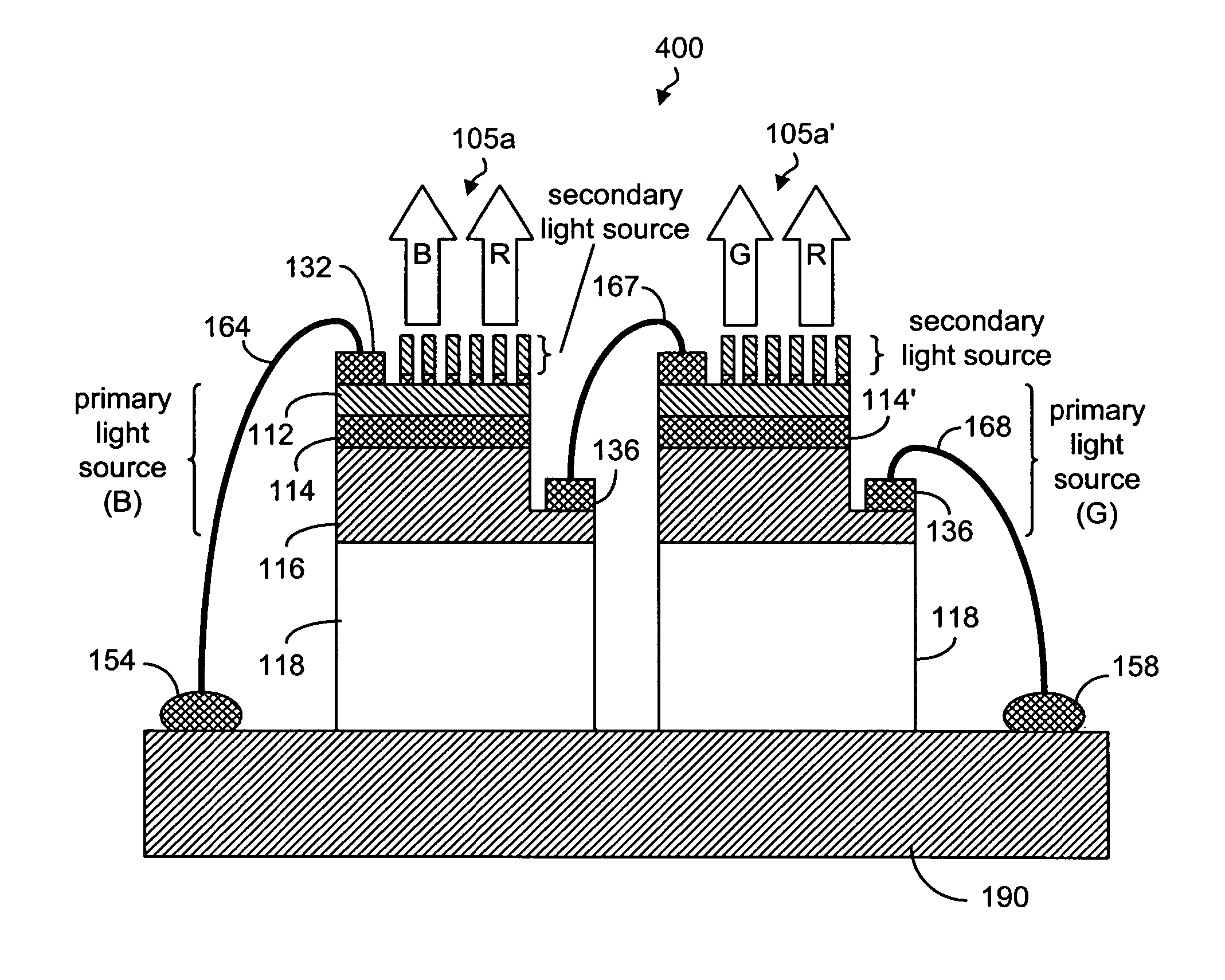
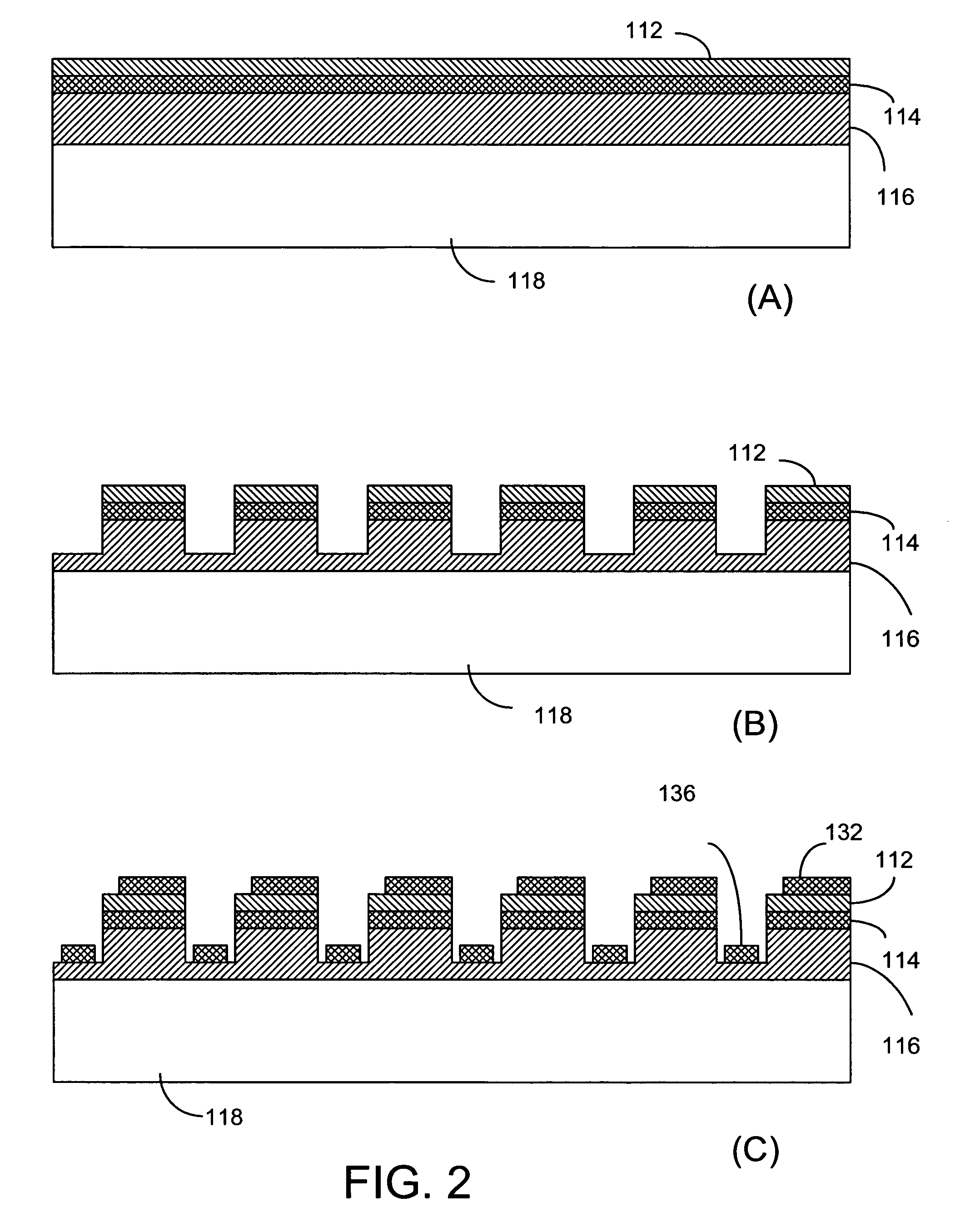
[0088]In order to achieve three primary colors red, green and blue in the white-light source, the present invention uses at least two discrete dual-color LEDs. A first dual-color LED emits red light and blue light, and a second dual-color LED emits red light and green light. As such, the combined light emission contains red light, green light and blue light. The present invention provides two distinct embodiments of the white-emitting light devices produced by two different methods. FIGS. 2a to 2h show a first method for producing dual-color LEDs, according to the present invention.

[0089]FIG. 2a shows various material layers disposed on a transparent substrate for producing a primary light source structure. As shown in FIG. 2a, an n-type GaN layer 116 is epitaxially grown on a sapphire substrate 118. A layer 114 of blue-light emitting InGaN is epitaxially grown on the n-type GaN layer 116 and then a p-type GaN layer 112 is epitaxially grown on the InGaN layer 114. The combined layer...


PUM


Abstract

A white-light emitting device comprising a first PRS-LED and a second PRS-LED. The first PRS-LED has a primary light source to emit blue light and a secondary light source to emit red light responsive to the blue light; and the second PRS-LED has a primary light source to emit green light and a secondary light source for emitting red light responsive to the green light. Each of the primary light sources is made from an InGaN layer disposed between a p-type GaN layer and an n-type GaN layer. The secondary light sources are made from AlGaInP. The primary light source and the secondary light source can be disposed on opposite sides of a sapphire substrate. Alternatively, the second light source is disposed on the n-type GaN layer of the primary light source. The second light sources may comprise micro-rods of AlGaInP of same or different compositions.

Description

[0001]This application is a continuation of application Ser. No. 11 / 035,647 filed on Jan. 14, 2005 now U.S. Pat. No. 7,045,375.FIELD OF THE INVENTION[0002]The present invention pertains to the field of semiconductor opto-electronic devices. More specifically, the present invention pertains to white light emitting diodes.BACKGROUND OF THE INVENTION[0003]Light emitting diodes (LEDs) are special types of semiconductor diodes first developed in the 1960s. A simplest LED consists of a p-type semiconductor and an n-type semiconductor forming a p-n junction. When an electric current passes through the junction, it creates charge-carriers (electrons and holes). In the process, an electron combines with a hole and releases energy in the form of a photon. Most of today's high efficiency LEDs have one or more layers of light emitting materials sandwiched between the p- and n-type regions to improve the light emitting efficiency. The layer structure is also used to obtain desired emission wavel...

Claims


Application Information

Patent Timeline
Patent Type & Authority Patents(United States)
IPC IPC(8): H01L21/00H01L33/00H01L25/075H01L33/08H01L33/50
CPCH01L25/0753H01L33/08H01L33/508H01L2224/48091H01L2224/48137H01L2224/48471H01L2224/49107H01L2924/00H01L2924/00014H01L2224/4554
Inventor WU, TUNG-HSINGHORNG, RAY-HUAWU, MENG-CHAI
Owner OPTRONIC SCI LLC
Why Eureka
Try Eureka