
Cross-correlation mitigation method and apparatus for use in a global positioning system receiver

a global positioning system and receiver technology, applied in the field of global positioning system receivers, can solve the problems of receiver never acquiring the sv, severe attenuation of the signal correlation process in the code-phase dimension by the resulting frequency response roll-off characteristics, and loss of the carrier frequency of the sv

Inactive Publication Date: 2007-04-24
QUALCOMM INC
View PDF7 Cites 25 Cited by
  • Summary
  • Abstract
  • Description
  • Claims
  • Application Information

AI Technical Summary

Benefits of technology

The patent describes a method and apparatus for reducing the effects of cross-correlation signals in a GPS receiver. The invention uses different levels of search modes, each with different coherent integration lengths and degrees of sensitivity, to detect and mitigate cross-correlation signals. The invention also includes several cross-correlation tests to identify the mainlobe, variable C / No, strong, and wide Doppler cross-correlation signals. The pre-emptive cross-correlation test prevents erroneous deletion of true energy peaks during the search process. The technical effects of the invention include improved accuracy and reliability of GPS navigation and positioning.

Problems solved by technology

If the receiver does not simultaneously adjust (or tune) its replica carrier signal during the code-phase (or range-phase) dimension acquisition and tracking process so that the replica carrier signal matches the frequency of the desired SV carrier, the signal correlation process in the code-phase dimension is severely attenuated by the resulting frequency response roll-off characteristics of the GPS receiver.
This has the consequence that the receiver never acquires the SV.
Further, if the SV signal is successfully initially acquired because the SV code and carrier frequency are successfully replicated during an initial search process, but the receiver subsequently loses track of the SV carrier frequency, then the receiver loses code track as well.
Under these conditions, the presence of the strong GPS signals produces interference that can reduce the ability to detect and track weaker GPS signals.
This cross-correlation can cause false acquisitions under certain Doppler difference and antenna gain conditions.
If the desired SV is low on the horizon, increased multi-path loss is present, as well as reduced GPS receiver antenna gain, which results in a typical net loss of 4 dB.

Method used


Image

  • Cross-correlation mitigation method and apparatus for use in a global positioning system receiver
  • Cross-correlation mitigation method and apparatus for use in a global positioning system receiver
  • Cross-correlation mitigation method and apparatus for use in a global positioning system receiver

Examples


first embodiment

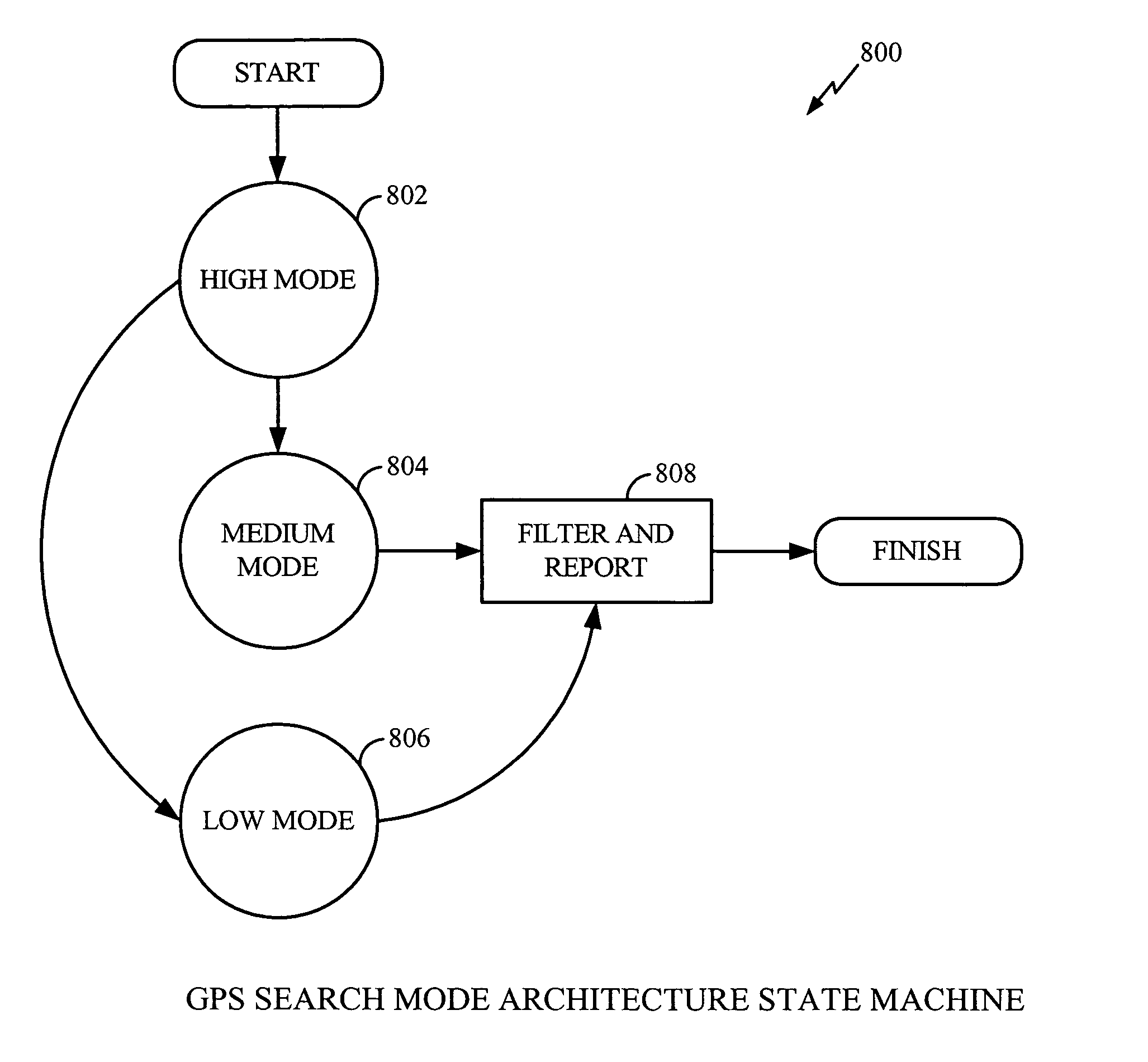
[0093]In one embodiment, GPS satellite signals are searched in accordance with a GPS Search Mode Architecture. The GPS search mode architecture is implemented in software and is resident in an integrated circuit (IC) within the GPS receiver. However, those skilled in the GPS communications and software design arts shall recognize that other embodiments of the GPS search mode architecture are possible and that the described embodiments should not be interpreted as limiting the scope or spirit of the present invention. In one embodiment, the GPS Search Mode Architecture includes different levels of search modes, each having different coherent integration lengths and varying degrees of sensitivity. For example, FIG. 8a is a simplified high level state machine 800 of the GPS search mode architecture adapted for use with the present invention. FIG. 8a shows the high level state machine of the search procedures to be followed when searching for SV satellite signals.

[0094]In accordance wit...

second embodiment

[0105]In accordance with the GPS search mode architecture, in the Level 1 (or Mode 1) search (state 802 of FIGS. 8a, 8b), the Code Phase and Doppler windows for each SV are enlarged and segmented. The Mode 1 search segments are then processed. A “max peak” algorithm is then performed for each search result. In one embodiment, once all search segments have been processed, the measurements are segmented into three satellite signal categories: “Strong”, “Weak”, and “None”. For example, in one embodiment, if the normalized peak energy for a given SV exceeds a predefined Level 1 threshold, then the measurement is classified as “Strong”. Otherwise, the measurement is classified as “Weak” or “None” depending upon whether a detectable measurement is found.

[0106]As described above with reference to the state machines of FIGS. 8a and 8b, once all of the searches have been processed, a variety of cross-correlation tests may be performed on the detected satellite signals (for example, at the st...


PUM


Abstract

A method and apparatus mitigating the effects of cross-correlation signals on received satellite signals in a Global Positioning System (GPS) receiver is described. MS-Assisted and MS-Based cross-correlation detection and mitigation methods and apparatus are described. A GPS search mode architecture is used to detect SV signals and identify potential cross-correlations. The GPS search modes have different coherent integration lengths and different degrees of sensitivity. After detection, measurements are logged into a database for further processing. Several cross-correlation tests are described. For example, a “Mainlobe” cross-correlation test is described that identifies the most significant cross-correlations that occur when the Doppler difference between the interfering SV signal and the target SV signal is nonzero and a multiple of 1 kHz. Appropriate C / No and Doppler thresholds, or masks, are selected and used to identify the mainlobe cross-correlations. A wide Doppler mask is used to account for the effects on cross-correlations caused by BPSK data bit modulation. Appropriate MS-Assisted and MS-Based cross-correlation masks are described. Other cross-correlation tests include “variable C / No”, “strong”, “wide Doppler” and “pre-emptive” cross-correlation detection tests.

Description

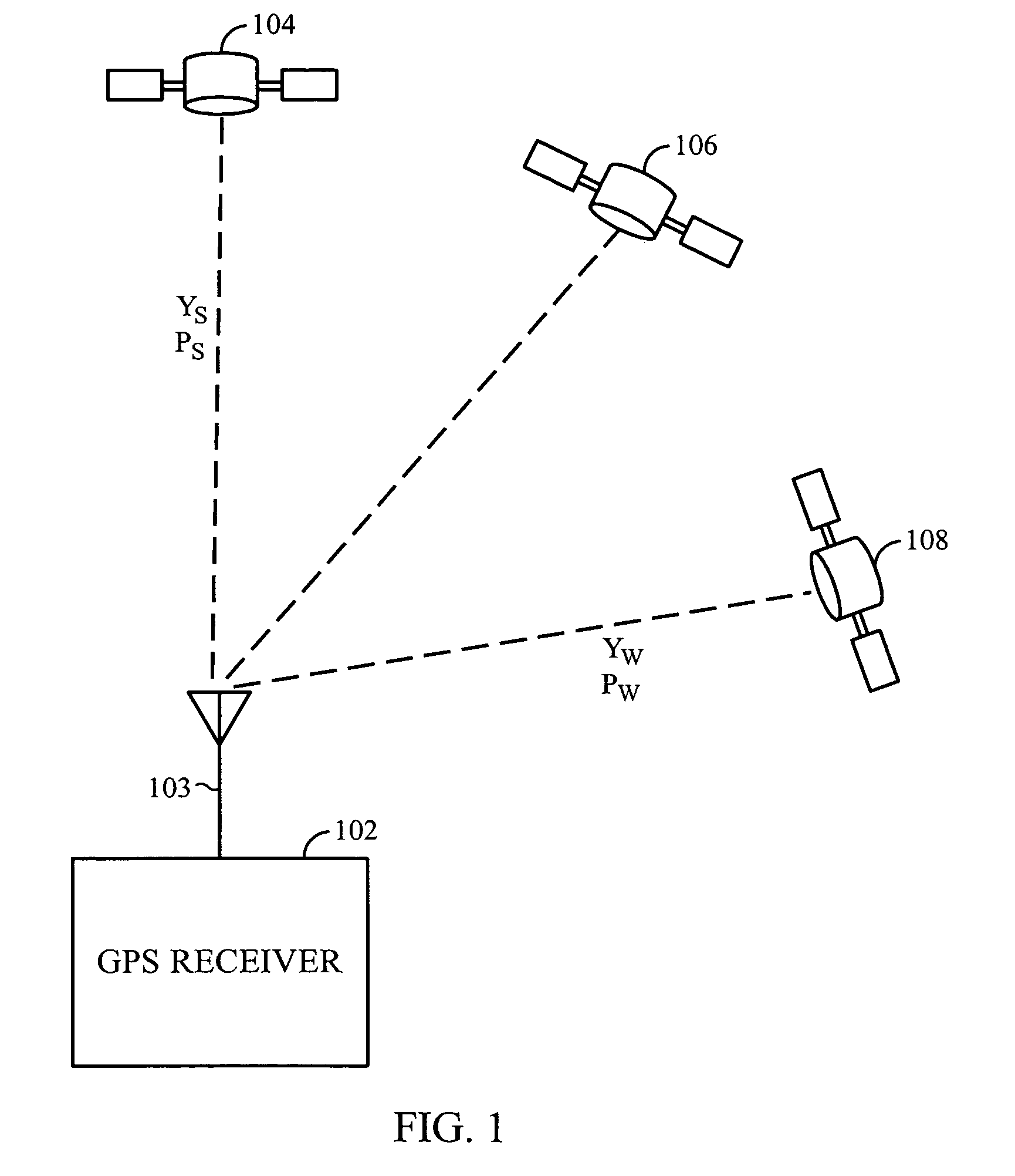
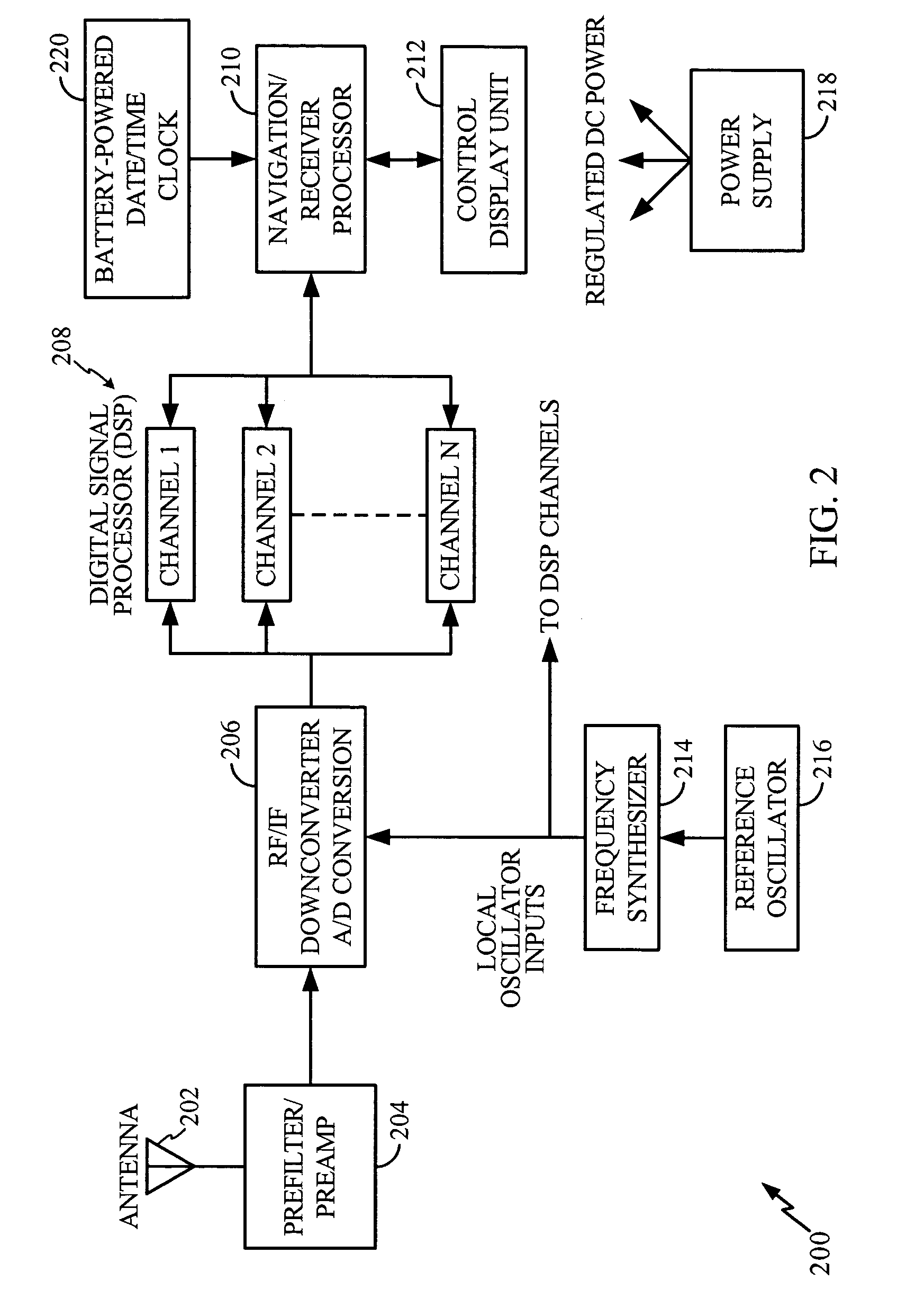
RELATED APPLICATIONS—CLAIM OF PRIORITY TO PRIOR APPLICATIONS[0001]This application is a Continuation-in-Part of U.S. application Ser. No. 10 / 618,184, filed Jul. 10th, 2003 now abandoned which claims the benefit of U.S. Provisional Application No. 60 / 395,217, filed on Jul. 10, 2002.BACKGROUND[0002]1. Field[0003]This disclosure relates generally to the field of global positioning system (GPS) receivers, and more particularly to a method and apparatus for mitigating satellite signal interference in a GPS receiver.[0004]2. Description of Related Art[0005]As is well known in the field of global positioning system (GPS) design, GPS receivers determine their position by computing the relative times of arrival (TOA) of signals that are simultaneously transmitted from a plurality of GPS satellites (also referred to herein as Space Vehicles (“SVs”)) orbiting the earth. As described in a related U.S. patent, U.S. Pat. No. 6,236,354, issued on May 22, 2001 to Krasner (referred to hereafter as t...

Claims


Application Information

Patent Timeline
Patent Type & Authority Patents(United States)
IPC IPC(8): G01S5/14H04B1/00G01S19/21G01S1/00G01S19/09G01S19/25G01S19/26G01S19/30
CPCG01S19/09G01S19/14G01S19/21G01S19/25G01S19/30
Inventor ROH, MARK CHARLES
Owner QUALCOMM INC
Learn More