Optical connector

a technology of optical connectors and connectors, applied in the field of optical connectors, can solve the problems of attenuation of signal level, limitation of cable length, and more inconvenience, and achieve the effect of accurate positioning and stably maintaining

Inactive Publication Date: 2007-05-01
SEIKO EPSON CORP
View PDF12 Cites 15 Cited by
  • Summary
  • Abstract
  • Description
  • Claims
  • Application Information

AI Technical Summary

Benefits of technology

[0009]According to this structure, an optical coupling is established through a plug or the like without adopting the structure in which an optical connection is established by directly contacting ends of optical transmission media such as optical fibers. Therefore, ends of the optical fibers are not required to be polished in high accuracy, and a cost increase due to a decrease in the yield can be avoided.
[0010]Moreover, because guide pins are not used for position adjustment between the female and made connectors, the number of parts is reduced, and the step for forming the guide pins becomes unnecessary, whereby an increase in the cost can be avoided. Therefore, low-cost optical connectors that are readily adopted for electronic equipments of household use can be provided.
[0012]According to this structure, miniaturization of an optical module becomes easy, and an optical module can be readily accommodated in a housing even when it is necessary to make the volume of the housing relatively small.
[0020]By this structure, the plug is placed substantially in a floating state, such that external forces acting on the optical transmission medium and the male connector become difficult to transmit to the plug. Also, because the force application device applies a force to the plug, there is provided an effect in that the plug and photoelectric conversion module on the side of the female connector can be accurately positioned, and its state can be stably maintained.

Problems solved by technology

However, in the aforementioned communications methods using electrical signals as communications media, the greater the transmission rates, the more inconveniences are caused, such as, generation of crosstalk between signal lines as a result of transmission signals being made a high frequency, attenuation of the signal level by impedance mismatch, limitation of the length of cables, and the like.
For this reason, it is considered to be difficult for the current technology to achieve high-speed communications at transmission rates that exceed 1 Gbps with practically reasonable costs.
However, it is undesirable to adopt optical connectors of the existing standards such as LC connectors and MT connectors in view of the costs.
When this polishing is conducted, in addition to the step of polishing ends of optical fibers, the steps of washing and testing are to be performed later, which would likely cause the yield to decrease, and becomes a factor to increase the cost.
Moreover, because the position adjustment between connectors (between a female connector and a male connector) is conducted with guide pins, the number of parts increases, and the step of forming the guide pins is also needed, which becomes an obstruction to the cost reduction.
By this structure, the plug is placed substantially in a floating state, such that external forces acting on the optical transmission medium and the male connector become difficult to transmit to the plug.

Method used


Image

  • Optical connector
  • Optical connector
  • Optical connector

Examples


Embodiment Construction

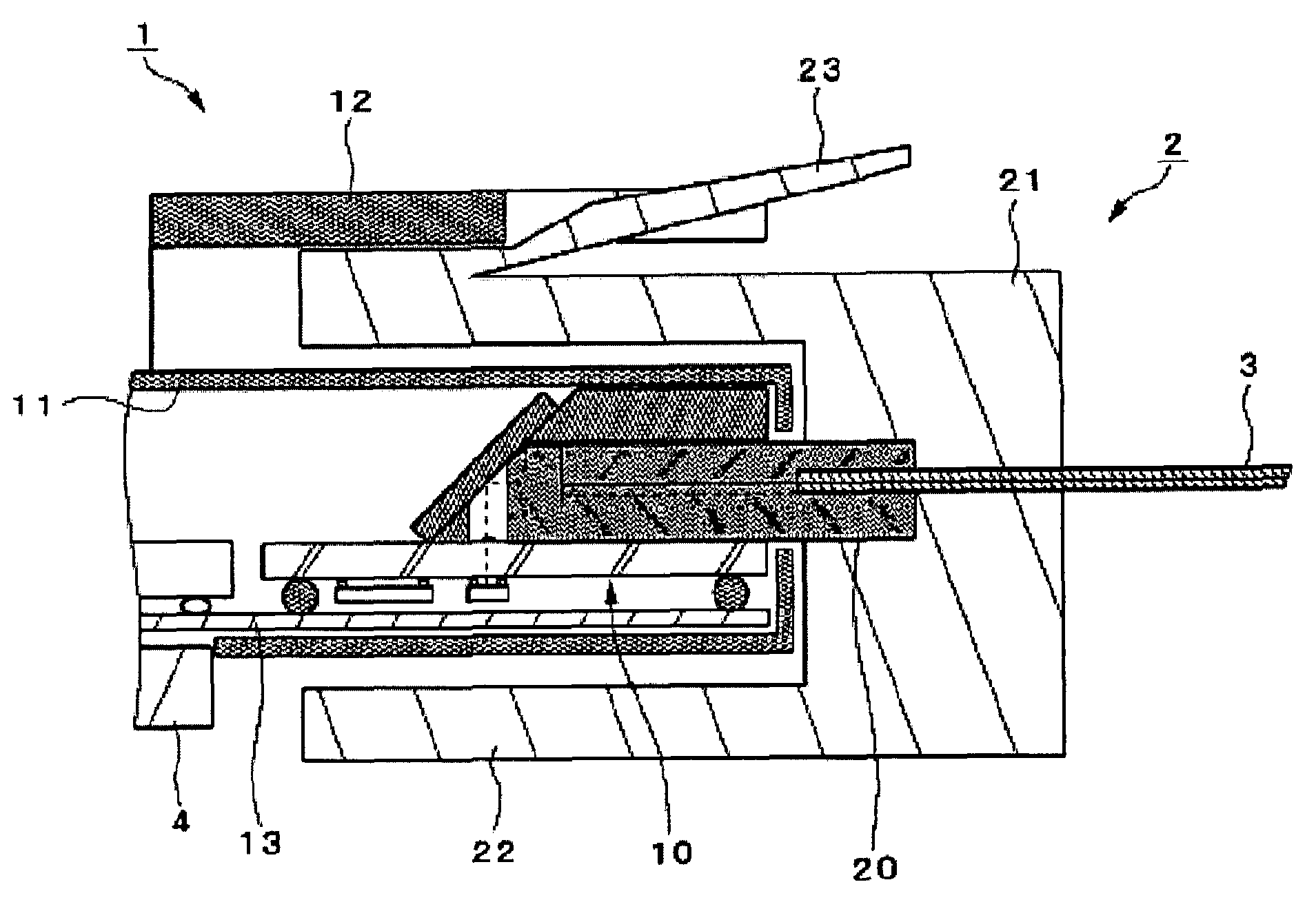
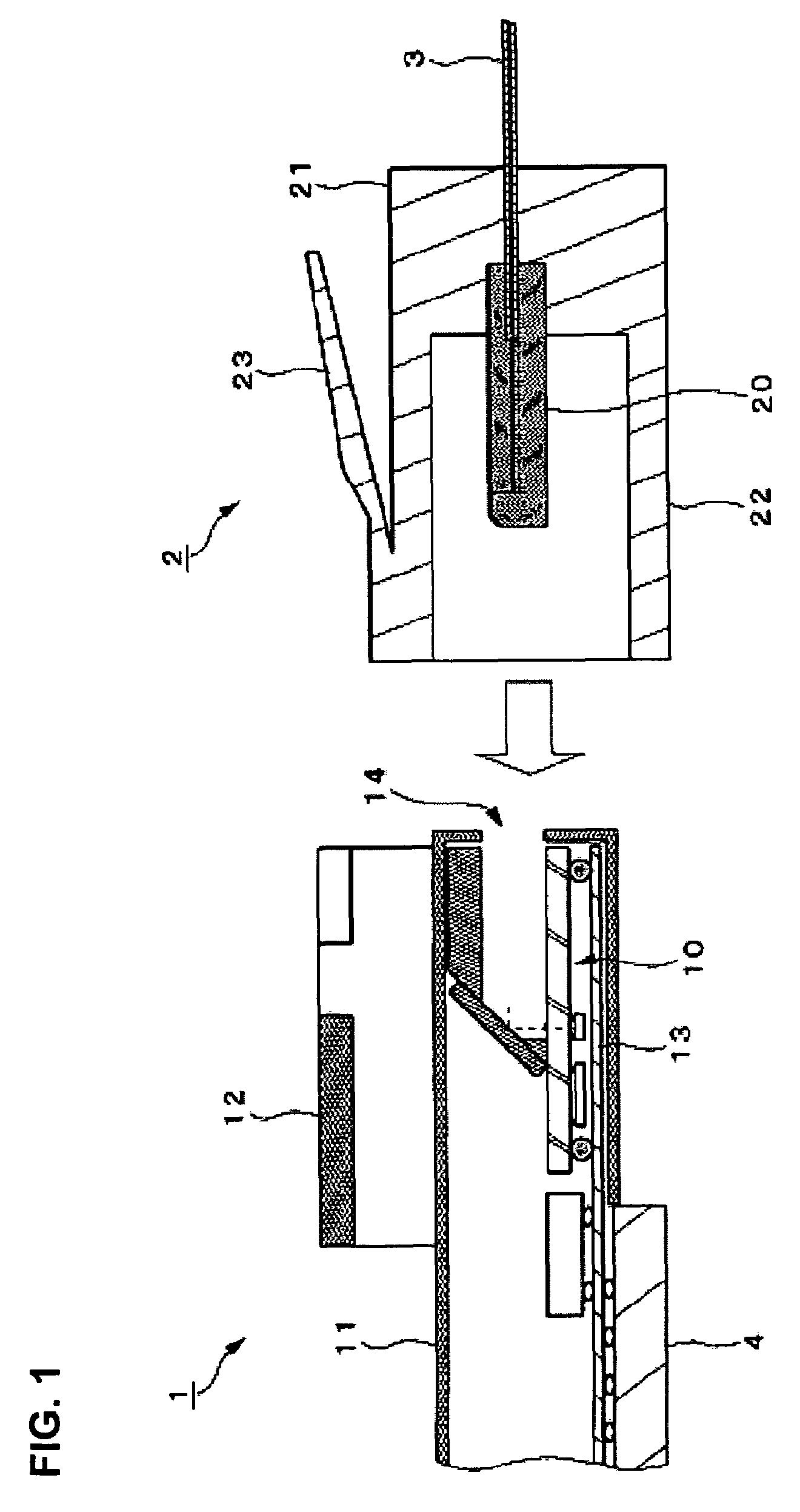
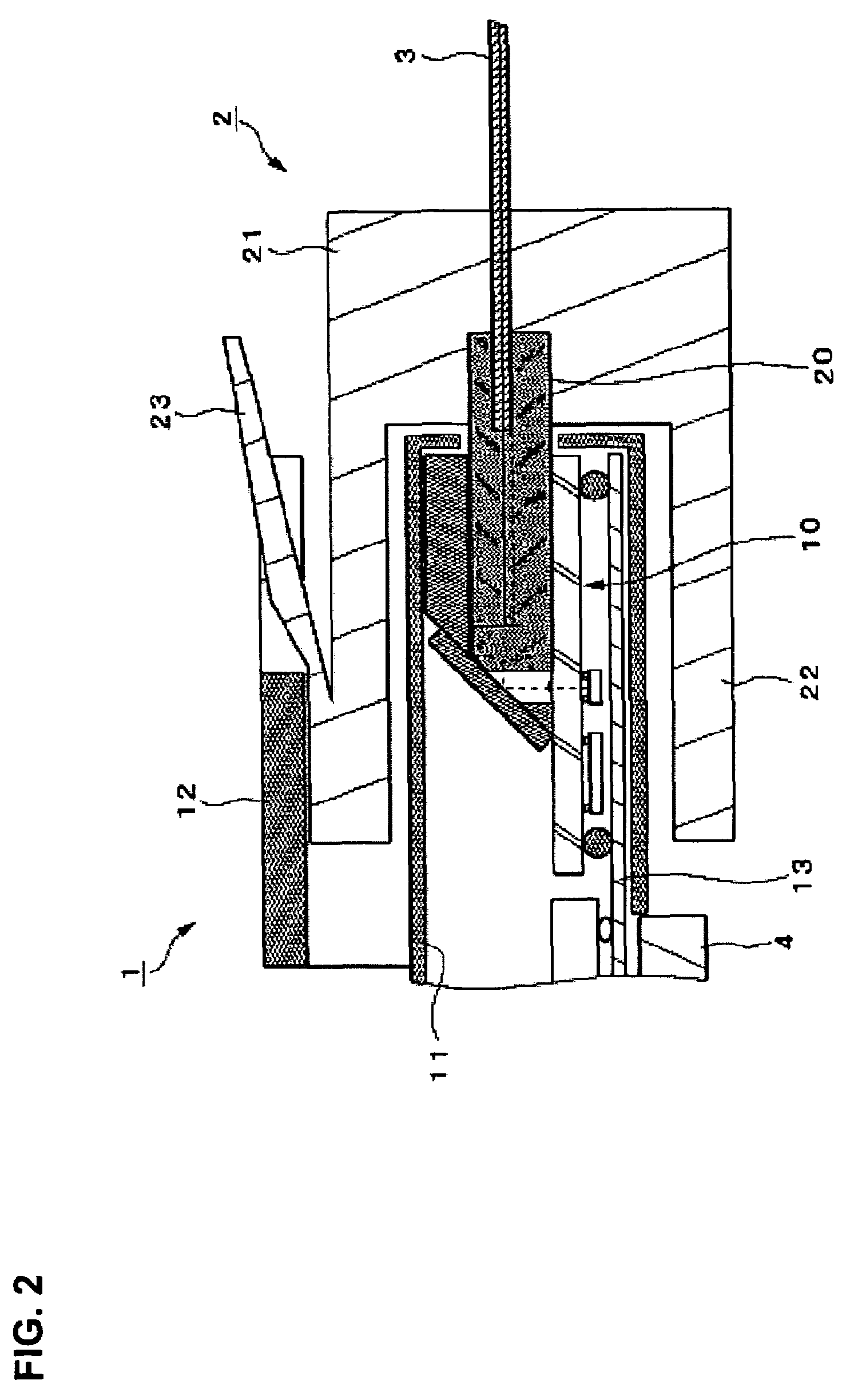
[0028]FIG. 1 shows views (cross-sectional views) for describing the structure of an optical connector in accordance with an embodiment of the present invention. The optical connector of the present embodiment shown in FIG. 1 is composed of a male connector 2 that supports a part of a tape fiber 3 (optical transmission medium), and a female connector 1 that is structured to be engageable with the male connector 2. Also, FIG. 2 is a view for describing the state in which the female connector 1 engages the male connector 2.

[0029]The female connector 1 includes a photoelectric conversion module 10, a housing (first housing) 11, a part to be latched 12 and a flexible wiring substrates 13, and may be mounted on an electronic equipment, such as, for example, a personal computer.

[0030]The photoelectric conversion module 10 has the function to convert an electrical signal to an optical signal and vice verse, and more specifically, has the function to convert an electrical signal into an opti...


PUM


Abstract

An optical connector comprising a male connector that supports one end of an optical transmission medium, and a female connector composed to be engageable with the male connector. The female connector includes a photoelectric conversion module having a function that mutually converts an electrical signal and an optical signal, and a first housing that accommodates the photoelectric conversion module and has an opening that communicates with the photoelectric conversion module accommodated, and the male connector has at least one portion that is inserted in the housing of the female connector through the opening, a plug having a function to optically connect the optical transmission medium and the photoelectric conversion module and provided at one end of the optical transmission medium, and a second housing that has an enclosure section provided around the plug while maintaining a space from the plug, and accommodates the plug.

Description

RELATED APPLICATIONS[0001]This application claims priority to Japanese Patent Application No. 2004-130207 filed Apr. 26, 2004 which is hereby expressly incorporated by reference herein in its entirety.BACKGROUND[0002]1. Technical Field[0003]The present invention relates to optical connectors that are used for systems that perform optical communications, and provide optical connection at coupling nodes of optical signals.[0004]2. Related Art[0005]Various telecommunications methods using electrical signals as media are standardized in order to perform mutual data communications among electronic equipments such as personal computers. For example, 10 BASE-T and 100 BASE-T according to the IEEE 802.3 standard are known as the telecommunications methods, which may be used for mutual data communications among computers, and among computers and peripheral equipments (for example, printers, and the like). In addition, higher transmission rates are desired along with the trend of performing d...

Claims


Application Information

Patent Timeline
Patent Type & Authority Patents(United States)
IPC IPC(8): G02B6/36G02B6/42G02B6/00G02B6/38H01L31/0232H01S5/022
CPCG02B6/4214G02B6/4249G02B6/4292G02B6/3821G02B6/3893G02B6/4206
Inventor NAGASAKA, KIMIOMIYAMAE, AKIRA
Owner SEIKO EPSON CORP
Why Eureka
Try Eureka