
Protective wind energy conversion chamber

a technology of wind energy conversion chamber and protection chamber, which is applied in the direction of renewable energy generation, electric generator control, greenhouse gas reduction, etc., can solve the problems of increasing the cost of wind energy conversion, so as to improve the efficiency

Active Publication Date: 2007-05-08
SCALZI SAVERIO
View PDF39 Cites 106 Cited by
  • Summary
  • Abstract
  • Description
  • Claims
  • Application Information

AI Technical Summary

Benefits of technology

"The present invention provides a wind energy conversion system with improved efficiency and safety. The wind energy conversion chamber allows for safe conversion of energy from a moving gas stream, such as a gust of wind or air current. The system can be safely deployed in high density areas, such as cities. The wind energy conversion chamber provides protection for people and animals interacting with it. The system can be adjusted to different wind flow directions and can be used in vehicles to produce supplemental electricity. The invention provides a method, system, and apparatus for wind energy conversion that overcomes the disadvantages of current wind energy conversion systems. The invention also includes a protective wind energy conversion chamber with a rotating or rotatable intake and exhaust, a converter, protective screens, and a turbine. The invention is not limited to the specific details shown and can be modified without changing the scope and range of equivalents of the claims."

Problems solved by technology

Unfortunately, much of this energy is supplied by nonrenewable resources whose relative availability continues to decrease.
Unfortunately, while the electricity generated by wind turbines use a clean, nonpolluting energy source, traditional wind turbine systems have a somewhat unexpected negative effect on the wildlife in the immediate environment, particularly on the local avian population.
Unfortunately, ninety-one percent of all documented avian incidents eventually resulted in mortality for the bird.
Unfortunately, none of the currently available systems can provide environmental protection for the surrounding avian population.

Method used


Image

  • Protective wind energy conversion chamber
  • Protective wind energy conversion chamber
  • Protective wind energy conversion chamber

Examples


Embodiment Construction

[0047]In the following description, numerous specific details are set forth. However, it is understood that embodiments of the invention may be practiced without these specific details. In other instances, well-known hardware, structures, and techniques have not been shown in detail in order not to obscure the understanding of this description.

[0048]Reference in the specification to “one embodiment” or “an embodiment” means that a particular feature, structure, or characteristic described in connection with the embodiment is included in at least one embodiment of the invention. The appearances of the phrase “in one embodiment” in various places in the specification do not necessarily all refer to the same embodiment.

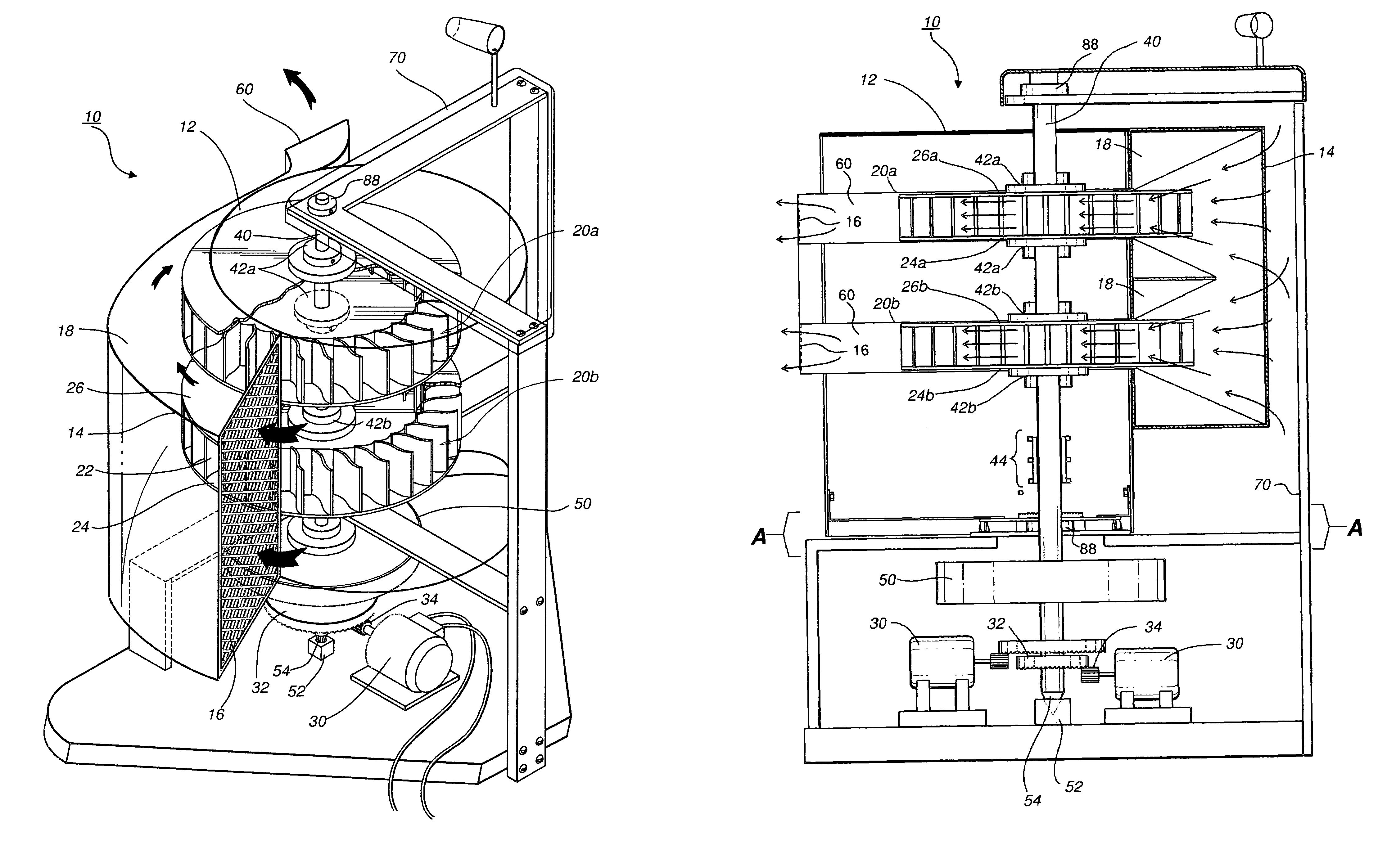
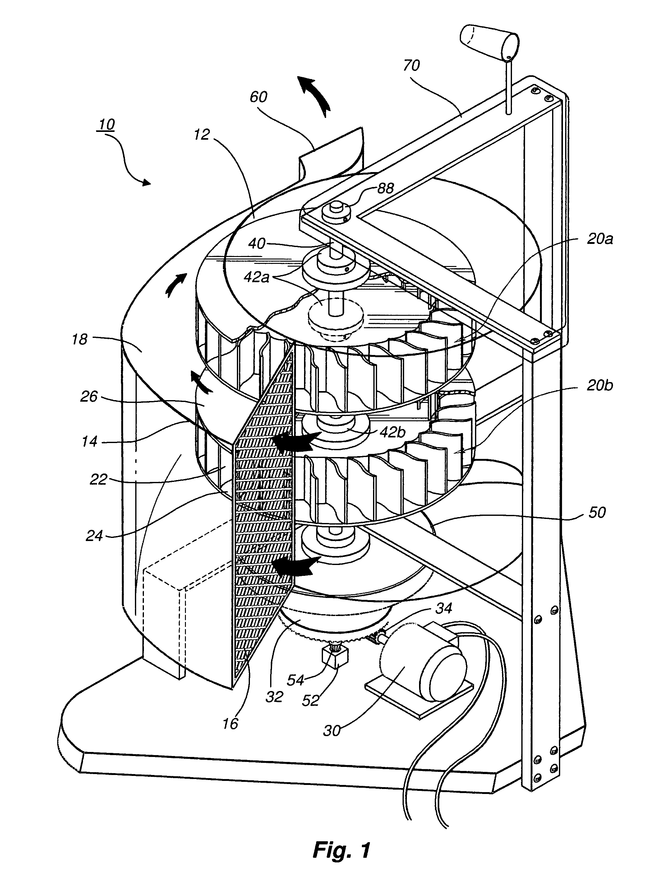
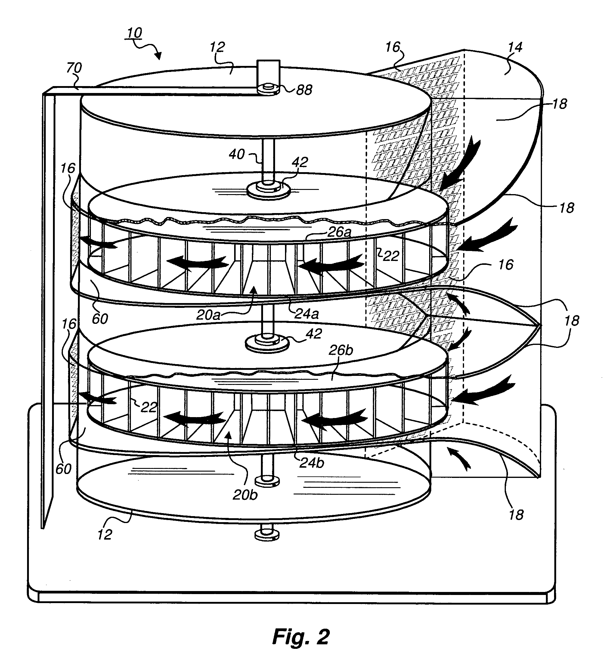
[0049]FIG. 1 and the following discussion are intended to provide a brief, general description of a suitable operating environment or wind energy conversion system 10. A wind turbine or wind energy conversion system 10 is a machine or mechanism that captures the force of...


PUM


Abstract

A protective wind energy conversion chamber provides a protected multiple turbine mechanism axially aligned to convert kinetic energy of a moving fluid (e.g., wind) into rotational mechanical power by the reaction of the moving fluid with the turbine. The conversion chamber may either be configured as a vertical axis wind turbine (VAWT) or horizontal axis wind turbine (HAWT). The conversion chamber repositions an intake windward to collect and concentrate the wind prior to converting the wind into energy via the axially aligned multi-turbine mechanism. The remaining wind is released via a leeward-facing exhaust. Completely enclosed by the protective wind energy conversion chamber, the axially aligned multi-turbine mechanism avoids interference by birds and other outside objects.

Description

FIELD OF THE INVENTION[0001]The present invention relates to wind energy conversion chambers. More particularly, the present invention relates to wind turbines used to generate electricity or drive other engines.BACKGROUND AND RELATED ART[0002]Energy needs of our society continue to grow at an increasing rate. Unfortunately, much of this energy is supplied by nonrenewable resources whose relative availability continues to decrease. Members of the power generation industry are gradually developing more efficient methods of power generation, with the ambition of one day generating their electricity from clean, sustainable renewable resources.[0003]One such potential area for expansion is wind energy. Wind turbines of various sizes and designs can mitigate our dependence on foreign energy supplies while providing distinct benefits to our domestic economy. Wind turbine designs may be optimized for particular locations and conditions. Moreover, wind turbines use the wind, a clean, nonpol...

Claims


Application Information

Patent Timeline
Patent Type & Authority Patents(United States)
IPC IPC(8): F03D9/00H02P9/04
CPCB60K16/00B60L8/00F03D1/04F03D3/0409F03D9/002B60K2016/006F05B2240/941Y02B10/30Y02E10/72Y02E10/74Y02T10/7083F03D9/25Y02T10/90F03D3/0463F03D9/30Y02T10/7072Y02E10/728
Inventor SCALZI, SAVERIO
Owner SCALZI SAVERIO
Learn More