Physically realistic computer simulation of medical procedures

a computer simulation and medical procedure technology, applied in the field of human/computer interface devices, can solve the problems of inability to inconvenient use of 2-dimensional input devices, and inability to meet the task of interfacing with 3-dimensional virtual reality simulations, and achieve low cost production, high reliability, and low inertia

Inactive Publication Date: 2007-05-08
IMMERSION CORPORATION
View PDF296 Cites 188 Cited by
  • Summary
  • Abstract
  • Description
  • Claims
  • Application Information

AI Technical Summary

Benefits of technology

[0016]The advantage of the present invention is that a 3-dimensional human/computer interface tool is provided which has the three or four degrees of freedom available that are desirable for many virtual reality simulation applications. The mechanism of the present invention is relatively straightforward allowing for low cost production and high reliability. Furthermore, since the human/computer interface tool of the present invention is constrained from movement along at certain degrees of freedom, it can more accurately simulate the use of tools and other elongated mechanical objects which are similarly constrained. Importantly, the present interface is of low inertia since the primary mass of the interface is located at the pivot point. This, along with the light

Problems solved by technology

However, 2-dimensional input devices tend to be awkward and inadequate to the task of interfacing with 3-dimensional virtual reality simulations.
W

Method used


Image

  • Physically realistic computer simulation of medical procedures
  • Physically realistic computer simulation of medical procedures
  • Physically realistic computer simulation of medical procedures

Examples


Embodiment Construction

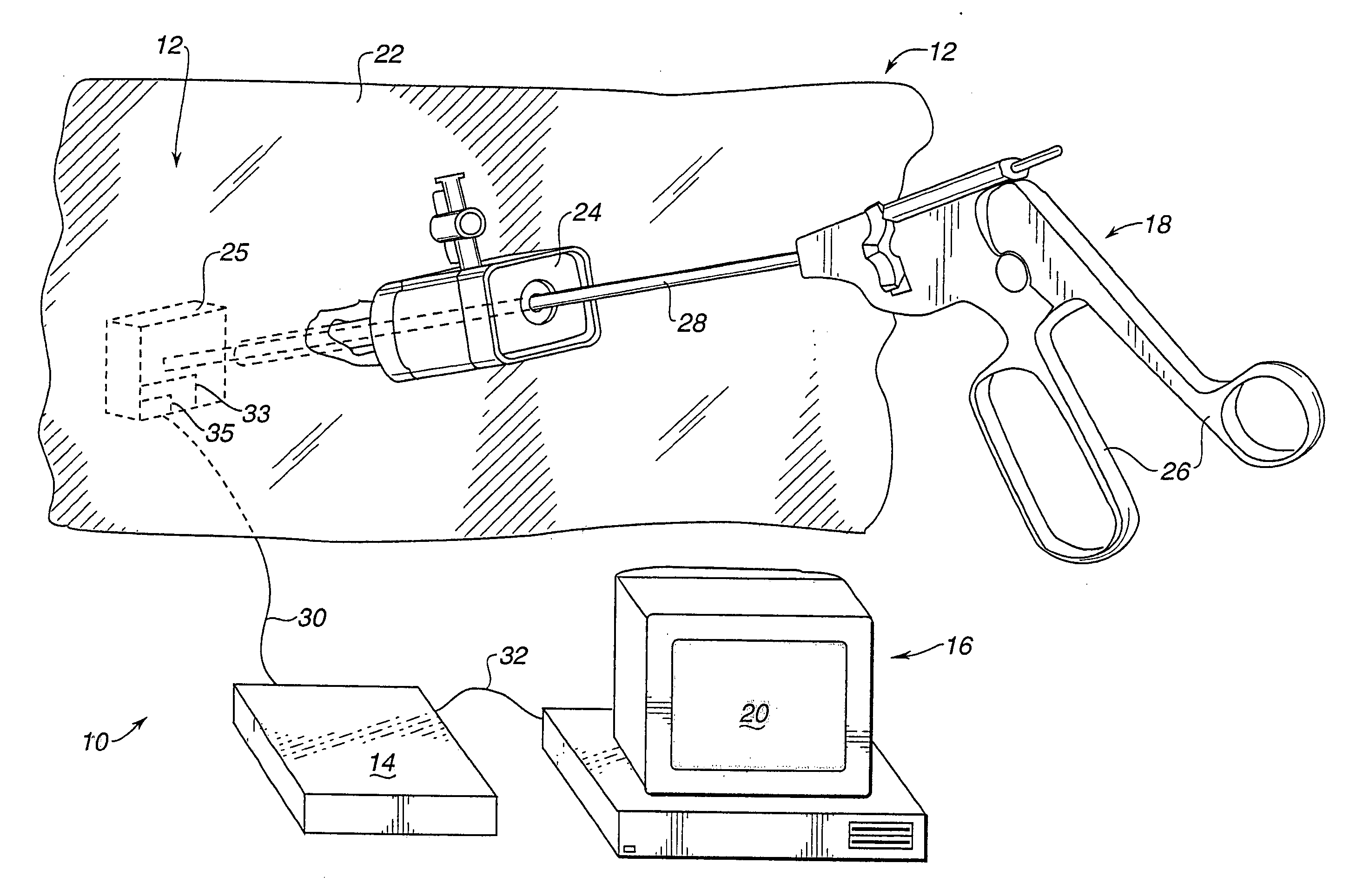
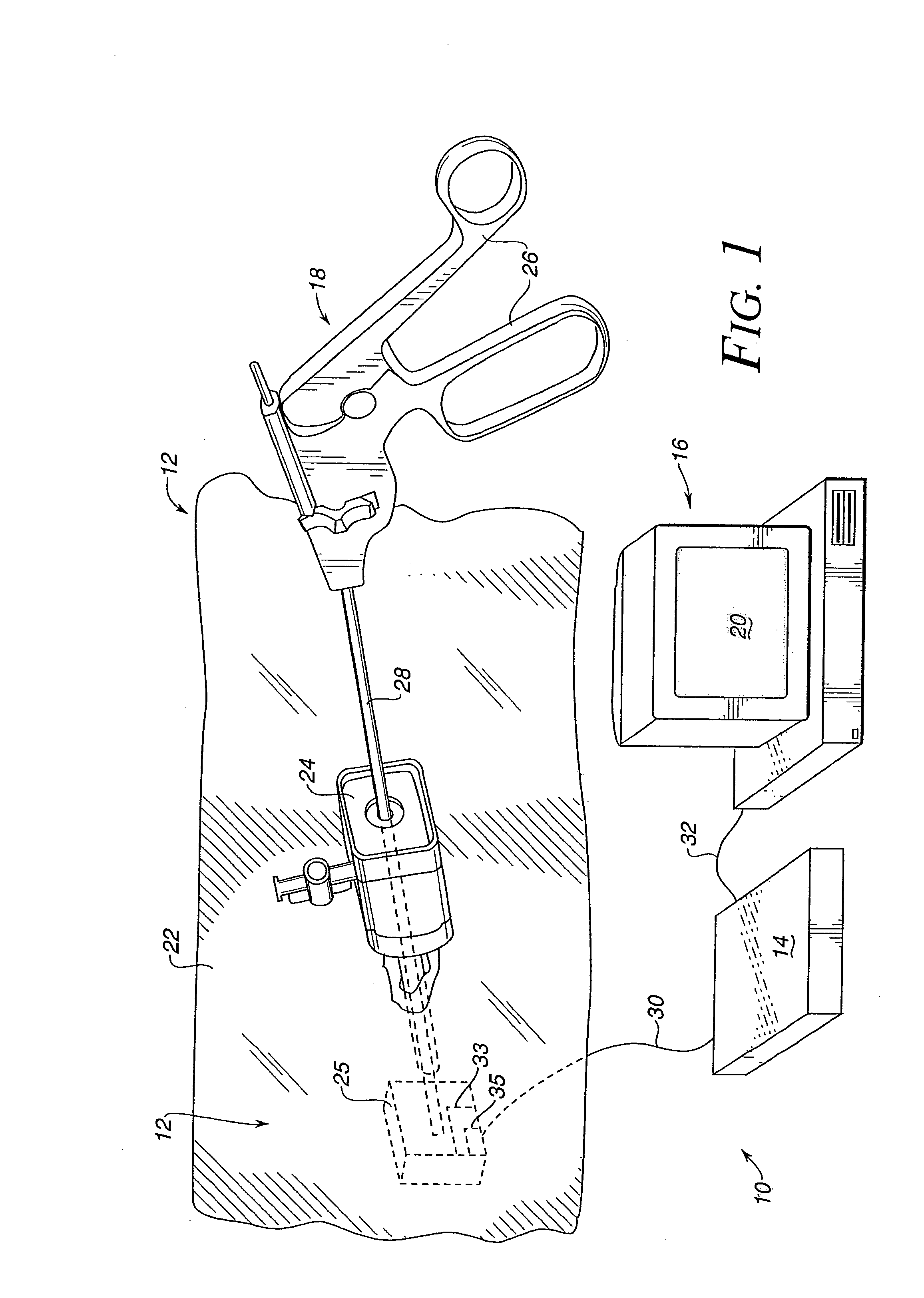
[0036]In FIG. 1, a virtual reality system 10 includes a human / computer interface apparatus 12, a electronic interface 14, and a computer 16. The illustrated virtual reality system 10 is directed to a virtual reality simulation of a laparoscopic surgery procedure. The software of the simulation is not a part of this invention and thus will not be discussed in any detail. However, such software is commercially available as, for example, Teleos™ from High Techsplanations of Rockville, Md. Suitable software drivers which interface such simulation software with computer input / output (I / O) devices are available from Immersion Human Interface Corporation of Palo Alto, Calif.

[0037]A laparoscopic tool 18 used in conjunction with the present invention is manipulated by an operator and virtual reality images are displayed on a screen 20 of the digital processing system in response to such manipulations. Preferably, the digital processing system is a personal computer or workstation, such as an...


PUM


Abstract

An apparatus for interfacing the movement of a shaft with a computer includes a support, a gimbal mechanism having two degrees of freedom, and three electromechanical transducers. When a shaft is engaged with the gimbal mechanism, it can move with three degrees of freedom in a spherical coordinate space, where each degree of freedom is sensed by one of the three transducers. A fourth transducer can be used to sense rotation of the shaft around an axis. The method includes the steps of defining an origin in 3-dimensional space, physically constraining a shaft in the 3-dimensional space such that a portion of the shaft always intersects the origin and such that a portion of the shaft extending beyond the origin defines a radius in a spherical coordinate system, transducing a first electrical signal related to a first angular coordinate of the radius with a first transducer, transducing a second electrical signal related to a second angular coordinate with a second transducer, transducing a third electrical signal related to the length of the radius with a third transducer, and coupling the transducers to a computer.

Description

[0001]This application is a continuation of U.S. application Ser. No. 09 / 996,487, filed Nov. 27, 2001, now U.S. Pat. No. 6,654,000, which is a continuation of U.S. application Ser. No. 09 / 276,012, filed Mar. 25, 1999, now U.S. Pat. No. 6,323,837, which is a continuation of application Ser. No. 08 / 833,502, filed Apr. 7, 1997 now U.S. Pat. No. 6,037,927, which is a continuation of application Ser. No. 08 / 275,120, filed Jul. 14, 1994, now U.S. Pat. No. 5,623,582, all of which are incorporated herein by reference in their entireties.BACKGROUND OF THE INVENTION[0002]This invention relates generally to human / computer interface devices, and more particularly to computer input devices such as mice, trackballs, etc.[0003]Virtual reality computer systems provide users with the illusion that they are part of a “virtual” environment. A virtual reality system will typically include a personal computer or workstation, specialized virtual reality software, and virtual reality I / O devices such as h...

Claims


Application Information

Patent Timeline
IPC IPC(8): G09G5/00A61B19/00B25J9/16G05B19/409
CPCB25J9/1689G05B19/409G06F19/3437A61B19/50A61B2019/2292G05B2219/35338G05B2219/35441G05B2219/40119G05B2219/40137G05B2219/45118A61B34/10A61B34/76G16H50/50
Inventor ROSENBERG, LOUIS B.
Owner IMMERSION CORPORATION
Why Eureka
Try Eureka