Moisture protection for an electromechanical transducer

a transducer and electromechanical technology, applied in the field of strain gauges, can solve the problems of unacceptably large influence of leakage currents, relative high absorption of water and solvents, and leakage currents, and achieve the effect of avoiding or avoiding

Active Publication Date: 2007-05-08
METTLER TOLEDO GMBH
View PDF17 Cites 7 Cited by
  • Summary
  • Abstract
  • Description
  • Claims
  • Application Information

AI Technical Summary

Benefits of technology

[0017]A strain gauge is disclosed that is or can be installed on a deformable body of a force-measuring cell, wherein a protective coating is provided which on the one hand prevents moisture from entering and on the other hand avoids or at least significantly reduces bypass forces.
[0019]The excellent barrier properties that are found in the inorganic materials are exploited and, by using very thin barrier coatings, a reduction of the very high stiffness associated with the thick inorganic coatings that are known from the existing state of the art is achieved. In order to avoid the aforementioned bypass forces, a coating thickness is selected primarily in the sub-micron range, because the inorganic materials, as is commonly known, have a modulus of elasticity that is larger by a factor of 10 to 100 than the elastic modulus of polymer materials of the kind that are used, e.g., for the carrier substrate. With a low thickness, it is possible to reduce the stiffness of the protective layer which, as is commonly known, depends on the elastic modulus of a material and on the thickness of a coating made of the material.
[0023]It is an exemplary property of the protective coating, specifically of individual layers of the latter, that the coating in the process of being deposited, particularly by PECVD (plasma-enhanced chemical vapor deposition), grows in a conformal way on the underlying surface, i.e., as a so-called conformal coating. This means that the surface receives a coverage of substantially constant thickness, independent of the angles at which individual surface locations are oriented in relation to the overall orientation of the deposition surface (plane of deposition). In other words, even overhanging portions or portions that substantially extend at a right angle to the deposition plane, for example the lateral flanks of the resistor track, are covered by the protective coating. In combination with the surface-smoothing polymer layer as an underlying base, an optimum of protection is achieved against the penetration of moisture. The polymer layer used as an undercoating under the protective coating has the effect of smoothing rough surface areas and rounding out edges where an inorganic protective coating has a particular tendency to develop the aforementioned micro-pores or micro-breaks, or hairline breaks that occur as a result of locally concentrated stresses, particularly thermal stresses, and where also on the other hand a tendency exists for micro-pores or micro-breaks to attach themselves. Thus, the occurrence of micro-pores or micro-fractures in the protective coating is a priori reduced, and while the edges still have a degree of steepness, they are not excluded from coverage by the protective coating, due to the conformance of coating to the underlying surface. Thus, the surface area of the strain gauge is covered completely and uniformly by the protective coating, and there are no weak spots where moisture could enter. In addition to the aforementioned complete coverage of the resistor track, the absence of weak spots is also of advantage in cases where the strain gauge is applied to a force-measuring cell and subsequently coated, or in a single-row array or a two-dimensional array of strain gauges in which the border surfaces of the carrier substrate are already substantially exposed by slits which were cut in the array to allow the border surfaces to be covered in the coating process.
[0029]This continuous variation can occur on the one hand in multilayered coatings as a soft transition between the individual layers, i.e., the coating parameters are not changing abruptly, but their profile is a continuous periodic function, rather resembling a sine function. On the other hand, the inhomogeneity can occur in a continuous transition over the entire thickness of the coating, as a gradient of one or more of the coating material parameters. This version of a continuous variation is, for example, advantageous for producing extremely thin protective coatings that are used on strain gauges for force-measuring devices of high sensitivity and a low load capacity.
[0031]An advantage of an inhomogeneous protective coating with a continuous variation of one or more parameters, whether the continuous variation has the form of a gradient or of continuous transitions between the layers of a multilayered coating, lies in a further reduction of internal stresses which could otherwise occur if layers with strongly different parameters followed each other abruptly in a multilayered coating, where the risk of a delamination of individual layers would not in all cases be excluded.
[0032]Accordingly, an advantage of a protective coating with a continuous variation of a parameter lies in a reduced risk of delamination. In contrast, an advantage of a multilayered coating with abrupt transitions between the layers lies in the fact that if a first layer, e.g., a barrier layer, is followed immediately by a second layer, e.g., an intermediate layer, with parameters different from the first layer, the micro-pores and micro-breaks of the first layer are almost completely covered, whereby an improved barrier effect is achieved.

Problems solved by technology

However, polymers have the disadvantage of a relatively high absorptiveness for water and also for solvents, so that the humidity of the ambient air surrounding the load cell, and more particularly a change in the relative humidity, has a lasting influence on the measuring result.
As a third factor, an increased moisture content of the substrate material can cause leakage currents between neighboring parts of a meander-shaped resistor track or even between the resistor track and the metallic deformable body.
While these effects are small in relation to the full-span signal, as shown by the aforementioned measurements, their influence on the measuring signal of a force-measuring cell that has to meet the highest accuracy requirements is nevertheless still unacceptably large.
The protection achieved by this dual-layer covering is not always satisfactory, in particular in highly sensitive force-measuring cells that are designed for relatively small loads.
The solutions of the foregoing description suffer from the problem that the protective coatings or protective foils which form a blanket cover over the strain gauge, in particular the inorganic coatings or foils with a strong barrier effect, have a comparatively large mass and a high degree of stiffness so that they, too, cause a change in the measuring result produced by the strain gauge.
This problem exists regardless of whether the protective coverings are applied directly to the strain gauge that is already installed on the measuring transducer or whether a covering is applied to a large number of strain gauges that have been produced together on one sheet.
This problem is particularly pronounced in force-measuring cells for the measurement of small forces, because the bending zones are in this case very thin in order to provide a high sensitivity.
Consequently, undesirable changes of the elastic properties of the protective covering, such as for example an elastic after-effect (also known as creep), a high inelastic component, in particular a strain hysteresis, cause a measurement error that is not reproducible and therefore not amenable to software-based compensation techniques.
In the interest of an economical use of materials, the thickness of the surface smoothing layer can however be limited to an amount that is consistent with achieving a desired degree of flatness.

Method used


Image

  • Moisture protection for an electromechanical transducer
  • Moisture protection for an electromechanical transducer
  • Moisture protection for an electromechanical transducer

Examples


Embodiment Construction

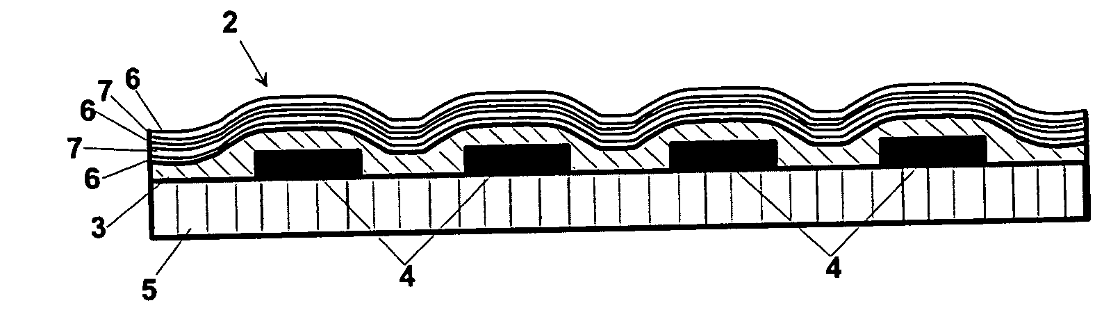
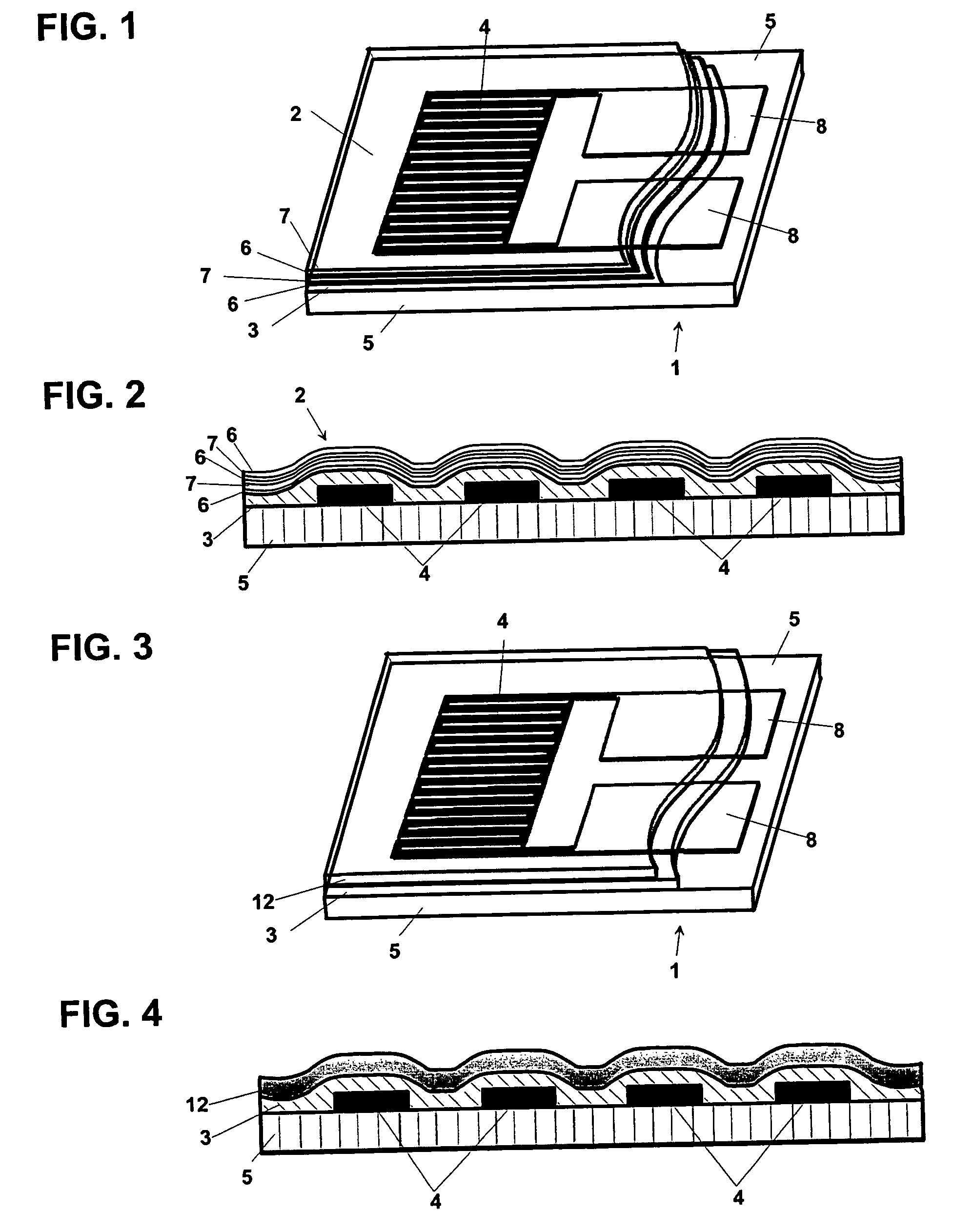
[0050]FIG. 1 is a three-dimensional illustration of an exemplary individual strain gauge 1 that is provided with a protective coating in the form of a multilayered coating 2 against the penetration of moisture, particularly of water vapors and solvent vapors, but also gases such as oxygen. The strain gauge 1 has a strain-sensitive resistor track 4 which is arranged, for example, in a meandering shape on a carrier substrate 5 and joined to connector electrodes 8. The strain gauge 1 was, for example, cut from a two-dimensional array of strain gauges after the coating process had been completed. For the sake of clarity, the multilayered coating 2, which includes, or consists of, a regular sequence of layers 6, 7, is shown transparent and broken open on one side. The layers 6, 7 of the multilayered protective coating 2 are of different inorganic materials or of different stoichiometric compositions of an inorganic material including, or consisting of, at least two components, or they ha...


PUM

PropertyMeasurementUnit
temperatureaaaaaaaaaa
humidityaaaaaaaaaa

Abstract

A strain gauge with a strain-sensitive electrical resistor track and connector electrodes for contacting the resistor track arranged on a carrier substrate is provided with a protective coating having inorganic materials and covering at least part of the carrier substrate and / or of the resistor track and / or of the connector electrodes. The build-up structure of the protective coating over the range of the coating thickness is inhomogeneous, and the protective coating is underlaid with a surface-smoothing polymer layer which evens out rough surface portions of the area to be coated. The layer thickness of the surface-smoothing layer is at least equal to the thickness of the protective coating. A strain gauge of this type can be used in a force-measuring cell, where the surface-smoothing layer and the protective coating can be deposited after an uncoated strain gauge has been installed on the deformable body of the force-measuring cell.

Description

RELATED APPLICATIONS[0001]This application claims benefit to European Priority Patent Application Serial Number 04 075 199.2, filed Jan. 27, 2004. This priority application is hereby incorporated by reference in its entirety.BACKGROUND[0002]1. Field[0003]A strain gauge is disclosed which has a strain-sensitive electrical resistor track arranged on a carrier substrate and connector electrodes for contacting the resistor track, wherein the strain gauge is provided with a protective coating of inorganic materials. An array of strain gauges is also disclosed that are arranged in a row or over an area, wherein the strain gauges have a strain-sensitive electrical resistor track arranged on a carrier substrate and a coating of inorganic materials covering the resistor track and at least part of the carrier substrate. A force-measuring cell with a deformable body and with at least one strain gauge arranged on the deformable body is also disclosed, as is a method of producing a protective co...

Claims


Application Information

Patent Timeline
Patent Type & Authority Patents(United States)
IPC IPC(8): G02B6/00G01B7/16G01G3/14G01L1/22
CPCG01G3/1402G01L1/2287
Inventor ZIEBART, VOLKERTELLENBACH, JEAN-MAURICE
Owner METTLER TOLEDO GMBH
Why Eureka
Try Eureka