Dynamic attitude measurement method and apparatus

Inactive Publication Date: 2007-05-08
ACEINNA TRANSDUCER SYST CO LTD
View PDF31 Cites 117 Cited by
  • Summary
  • Abstract
  • Description
  • Claims
  • Application Information

AI Technical Summary

Benefits of technology

[0008]In one embodiment of the present invention, a relatively inexpensive and compact-sized system generates an accurate representation of an attitude of an object. In particular, the system measures attitude for an object that may be accelerating, thereby overcoming the drawbacks of conventional attitude measuring devices mentioned above. Furthermore, such embodiment of the present invention provides a self-tuning system that automatically compensates for drift and that automatically updates the quaternion obtained from sensor outputs. The syst

Problems solved by technology

However, the mass of a pendulum renders such devices also responsive to acceleration, and hence are not useful as attitude sensors in dynamic systems involving an accelerating body.
Similarly, liquid sensors exhibit mass that affects attitude detection during acceleration, and also such sensors are vulnerable to vibration that affects surface characteristics of the liquid upon which sensing may depend.
Vertically-oriented spinning gyroscopes commonly operate as attitude sensors, but are usually heavy, bulky, expensive devices that are subject to precession and drift errors.
They also suffer from poor reliability in rugged operat

Method used


Image

  • Dynamic attitude measurement method and apparatus
  • Dynamic attitude measurement method and apparatus
  • Dynamic attitude measurement method and apparatus

Examples


Embodiment Construction

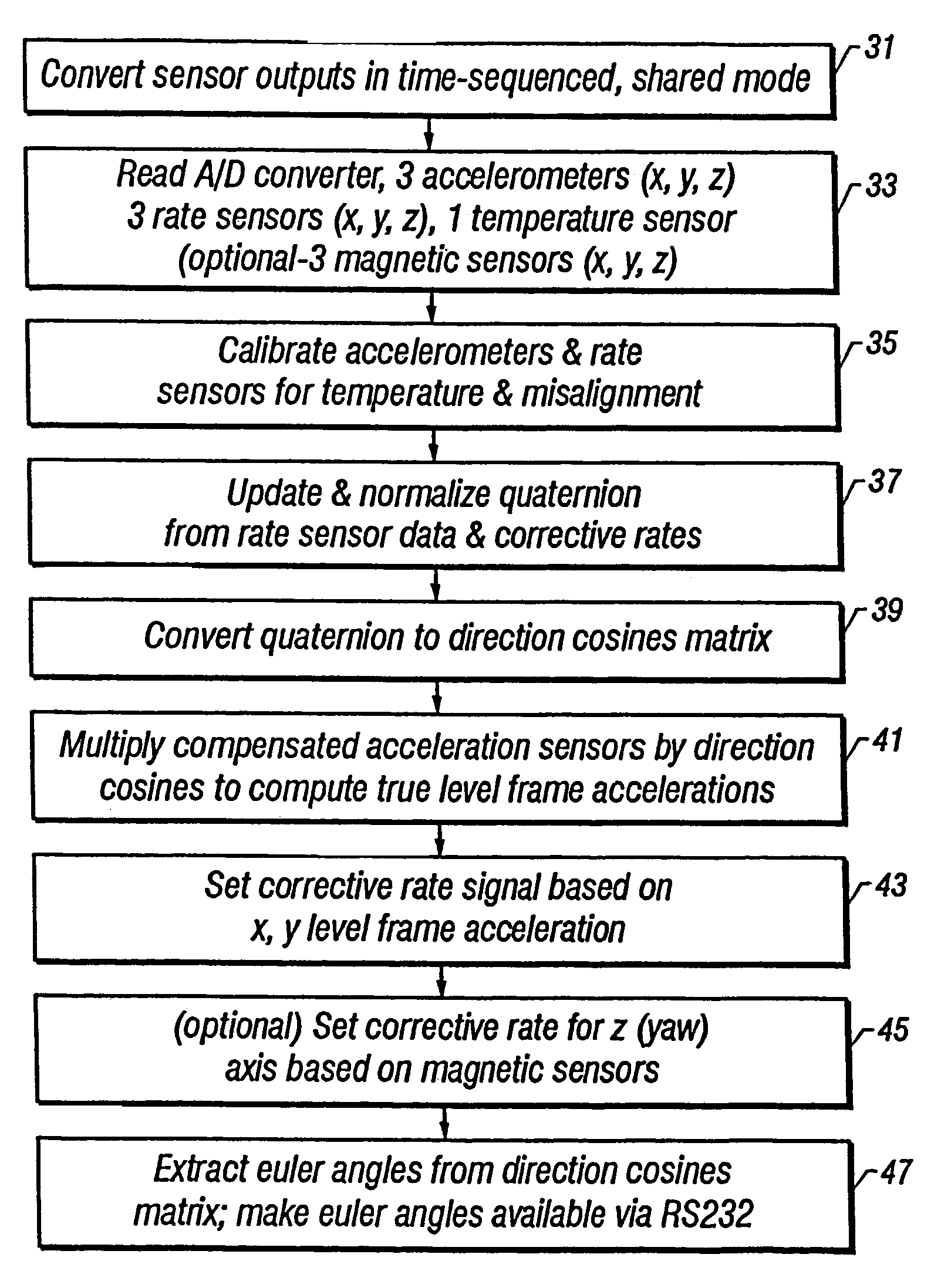
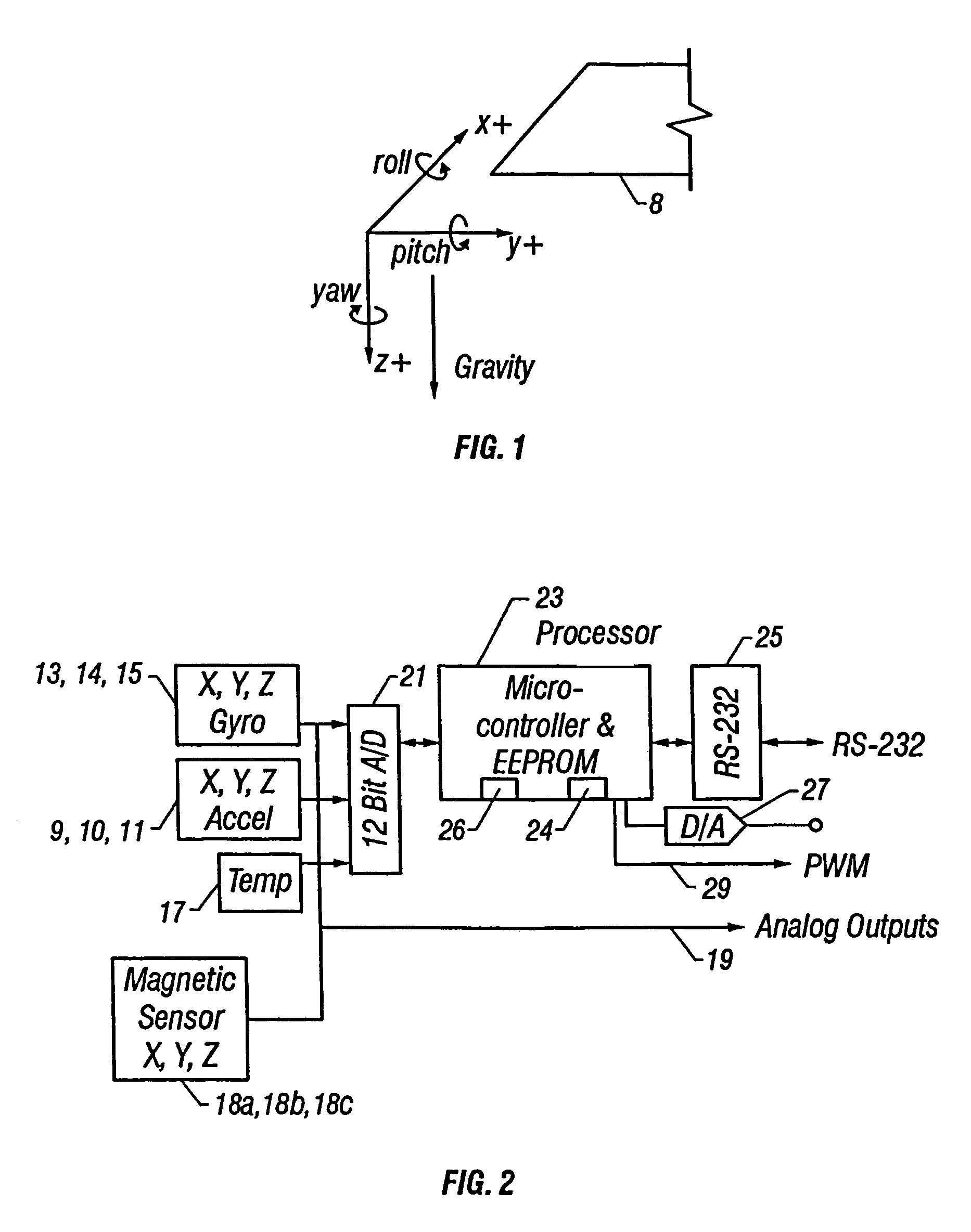
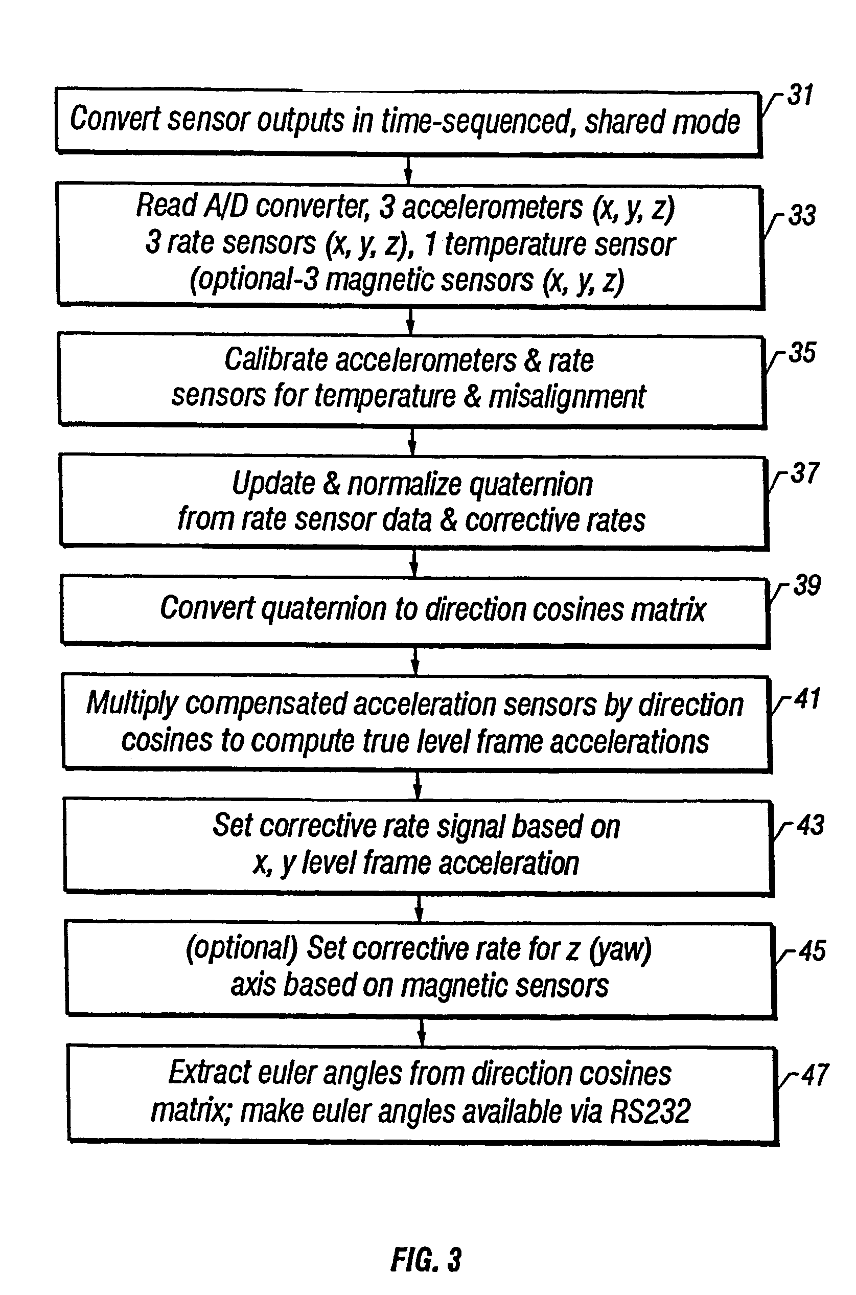
[0024]Referring now to the graph of FIG. 1, there is shown a coordinate set of axes X, Y, and Z that designate directions of movement or orientations with respect to the ‘horizon’8 as a reference plane, and about which rotational motions are specifically legend as ‘pitch’ (i.e., rotation about Y in the XZ plane), and ‘roll’ (i.e., rotation about X in the YZ plane), and ‘yaw’ (i.e., rotation about Z in the X Y plane, also referenced as ‘heading’ or ‘azimuth’).

[0025]In accordance with the present invention, as illustrated in the block diagram of FIG. 2, solid-state accelerometers 9, 10, 11 are disposed in alignment with each of the X, Y, and Z axes, respectively, and inertial elements 13, 14, 15 are disposed to sense rate of change of angular displacement about each of the X, Y, and Z axes, respectively. The accelerometers 9–11 may each comprise conventional micro-machined silicon devices that operate on differential capacitance to produce an analog output indication of axial accelera...


PUM


Abstract

A method and system senses the attitude of an accelerating object by measuring acceleration with accelerometers in three orthogonal axes and measuring angular rate with angular rate sensors disposed about each such axis to compute attitude of the object accurately relative to a vertical axis. A processor updates a quaternion representation of attitude based upon the angular rate of the object, and a corrective rate signal is determined from level frame acceleration as a reference for a Kalman filter in calculating the attitude of the object. When velocity or airspeed is available from an external source, an aiding algorithm is employed to provide accurate attitude representations throughout all flight regimes.

Description

RELATED APPLICATIONS[0001]This application is a continuation-in-part of U.S. Pat. No. 6,853,947 which is a continuation of U.S. Pat. No. 6,647,352, which is a continuation-in-part of U.S. Pat. No. 6,421,622, which claims priority from U.S. Provisional Application Ser. No. 60 / 088,160, filed on Jun. 5, 1998, by Michael A. Horton, entitled “DYNAMIC ATTITUDE MEASUREMENT SENSOR AND METHOD”, which applications are fully incorporated herein by reference.FIELD OF THE INVENTION[0002]This invention relates to the measurement of attitude of accelerating bodies, and more particularly to attitude sensors and control systems.BACKGROUND OF THE INVENTION[0003]Certain known techniques for measuring and controlling attitude of a moving body commonly rely upon a gyroscope spinning about a vertical axis, or upon a liquid sensor, or upon a pendulum device responsive to downward gravitational orientation. However, the mass of a pendulum renders such devices also responsive to acceleration, and hence are ...

Claims


Application Information

Patent Timeline
IPC IPC(8): G06F15/00
CPCG01C21/16G01S19/49G01C21/183
Inventor HORTON, MICHAEL A.RIOS, JOSE
Owner ACEINNA TRANSDUCER SYST CO LTD
Why Eureka
Try Eureka