Tool holder for cutting bodies

a tool holder and cutting body technology, applied in the direction of turning tools, adverse effects compensation, turning tools, etc., can solve the problems of increased production costs, adverse effects on the accuracy of machining with indexable inserts seated in the tool holder, etc., and achieve the effect of high-precision machining and cost-effective production of the tool holder

Inactive Publication Date: 2007-05-15
HARTMETALL WERKZEUGFAB PAUL HORN
View PDF8 Cites 20 Cited by
  • Summary
  • Abstract
  • Description
  • Claims
  • Application Information

AI Technical Summary

Benefits of technology

[0007]Objects of the present invention are to provide an improved tool holder for cutting elements so that the bearing component is configured to have an especially reliable mounting on the base holder and to have high-precision machining, and production of the tool holder is nevertheless cost effective.

Problems solved by technology

The tilting results in an adverse effect on the accuracy of machining with the indexable inserts seated in the tool holder, since the latter also are also tilted and accordingly displaced in their machining plane.
In addition, because of the gear cutting geometries, the disclosed solution results in increased production costs, in particular if the respective toothing is to be produced as high-precision toothing.

Method used


Image

  • Tool holder for cutting bodies
  • Tool holder for cutting bodies
  • Tool holder for cutting bodies

Examples


Embodiment Construction

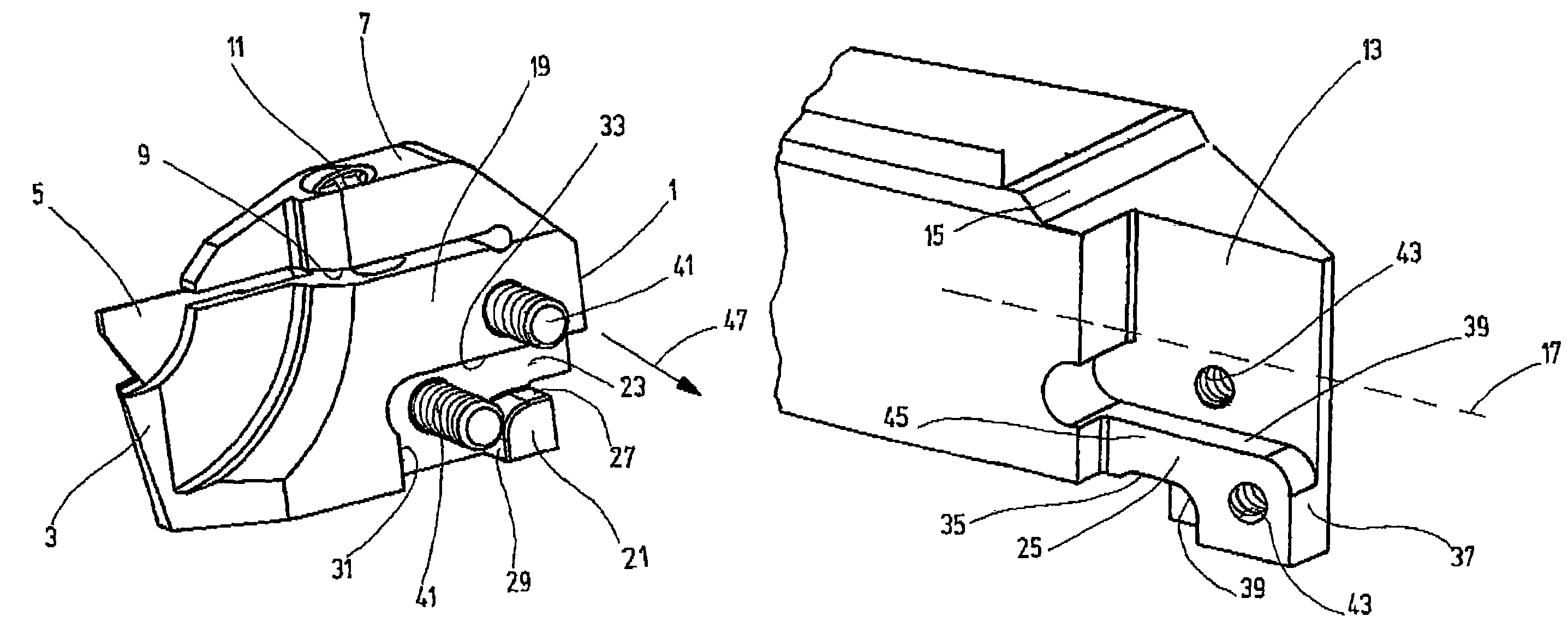
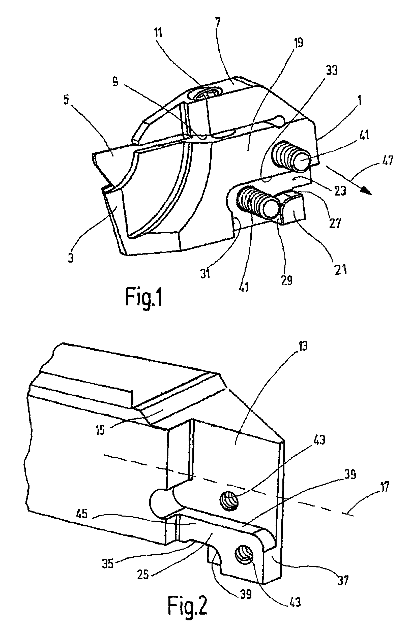
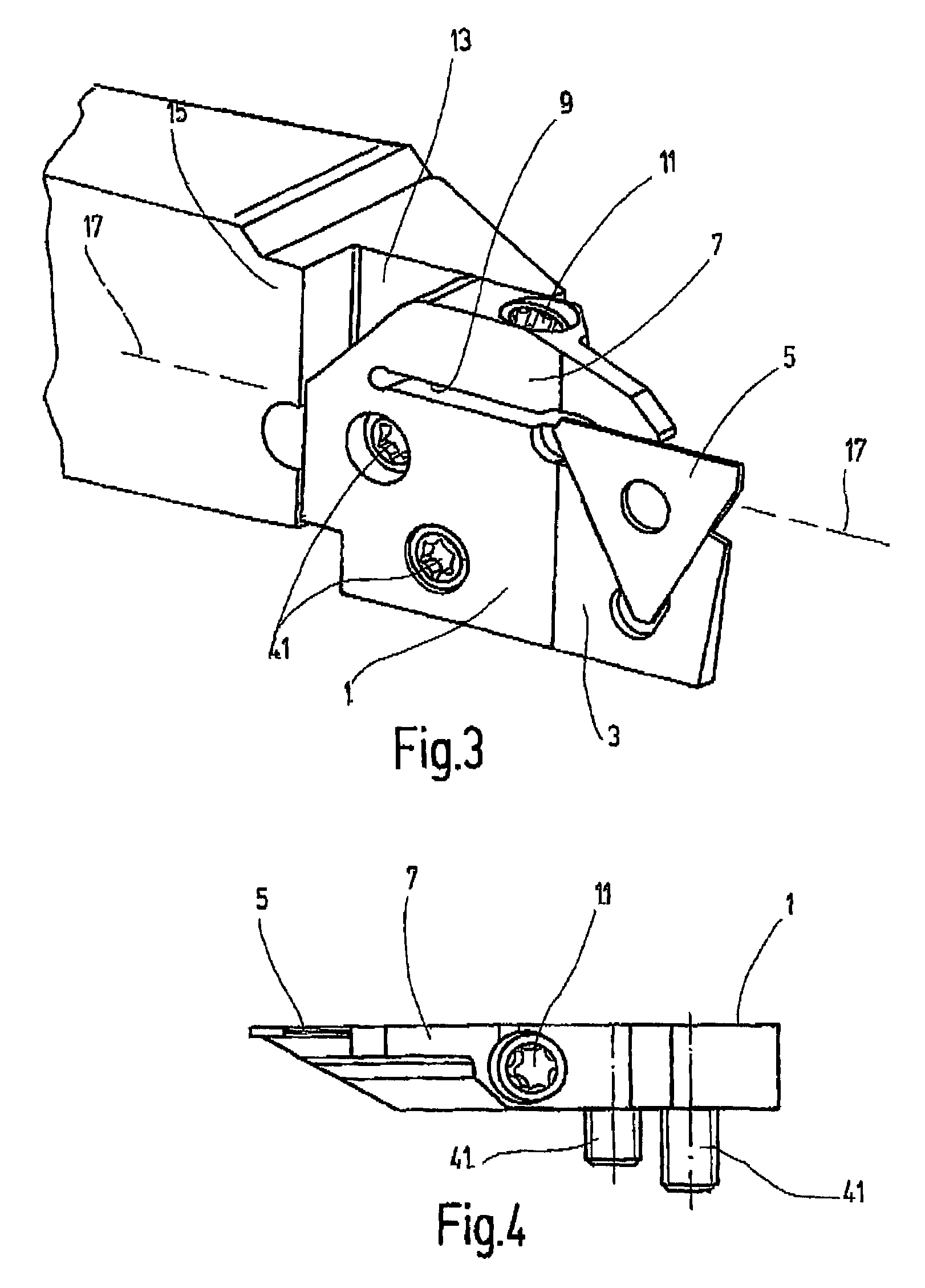
[0018]A tool holder according to an embodiment of the present invention is described on the basis of as a holder represented by a clamping holder. The holder has a base component 1 which has in the area of its front end a seating adapter 3 with a seat as receptacle for a commercially available indexable insert 5. A clamping jaw 7, integral with the base component 1, is mounted on this base component 1 and projects forming a clamp opening 9. The clear span of the clamp opening may be reduced by an attachment screw 11 extending through the clamp opening to immobilize the indexable insert 5 in its seat in the seating adapter 3 by pressing the clamping jaw 7 against this indexable insert 5.

[0019]As is to be seen in the figures (see FIG. 3 in particular), the opposite wider side of the base component 1 may be mounted on a tool seat 13 of a base holder 15. Only the front end area of the base holder with the tool seat 13 is shown in FIGS. 2 and 3. In the part not shown, the base holder 15 ...


PUM

PropertyMeasurementUnit
anglesaaaaaaaaaa
cutting forcesaaaaaaaaaa
torsional forcesaaaaaaaaaa

Abstract

Tool holder for cutting bodies (5) may be mounted on a base holder (15) by a fixing device (41), and a cooperating stop extending in a plane in the direction of the tool holder. A positive positional fixing against any movement along the three axes of the spatial coordinate system may be obtained. The planar stop is divided into planar sections (19, 21) by a machined recess (23). The recess (23) forms a seat for housing a projecting matching body (25) on the base holder (15). The walls of the recess (23) form planar support surfaces (31, 33) for the matching body (25), which each define differing planes perpendicular to the stop, to resist displacement and torsional forces resulting from the cutting force into the matching body (25) of the base holder (15).

Description

FIELD OF THE INVENTION[0001]The present invention relates to a tool holder for cutting bodies, particularly indexable inserts. The tool holder may be mounted on a base holder by a fastening device. A bearing component operates in conjunction with and extends in a level configuration in the direction of the tool holder. The cutting forces generated by the cutting element are introduced into the base holder by the bearing component.BACKGROUND OF THE INVENTION[0002]DE 40 24 096 C2 discloses a tool holder having a cutting tool for metal cutting, a minicutter bar in particular. A cutting insert is braced by a clamping leg resting against it on a flat clamping surface in a recess having cutting insert mounting surfaces of a lengthwise slotted forked holder shaft. In the disclosed solution, the clamping surface of the cutting insert is positioned in parallel with the axis of the holder shaft. The recess in the holder shaft has three cutting insert bearing surfaces, specifically, a bottom s...

Claims


Application Information

Patent Timeline
Patent Type & Authority Patents(United States)
IPC IPC(8): B23B29/04B23B29/00B23B27/04
CPCB23B27/04B23B2210/08Y10T407/2288Y10T407/227Y10T407/25B23B2250/12
Inventor OETTLE, MATTHIAS
Owner HARTMETALL WERKZEUGFAB PAUL HORN
Why Eureka
Try Eureka