Capillary tubing
a tubing and capillary technology, applied in the field of capillary tubing, can solve the problems of limited flexibility in the choice of jet dimensions, speed and jet material, and the limited range of usable target materials, and achieve the effect of reducing the pollution of the passageways in the supply system of target material, and reducing the cost of target material
- Summary
- Abstract
- Description
- Claims
- Application Information
AI Technical Summary
Benefits of technology
Problems solved by technology
Method used
Image

Examples
examples
[0046]In the following, some preferred implementations utilizing a capillary tubing according to the present invention will be described. Again, general reference is made to FIG. 3 of the accompanying drawings.
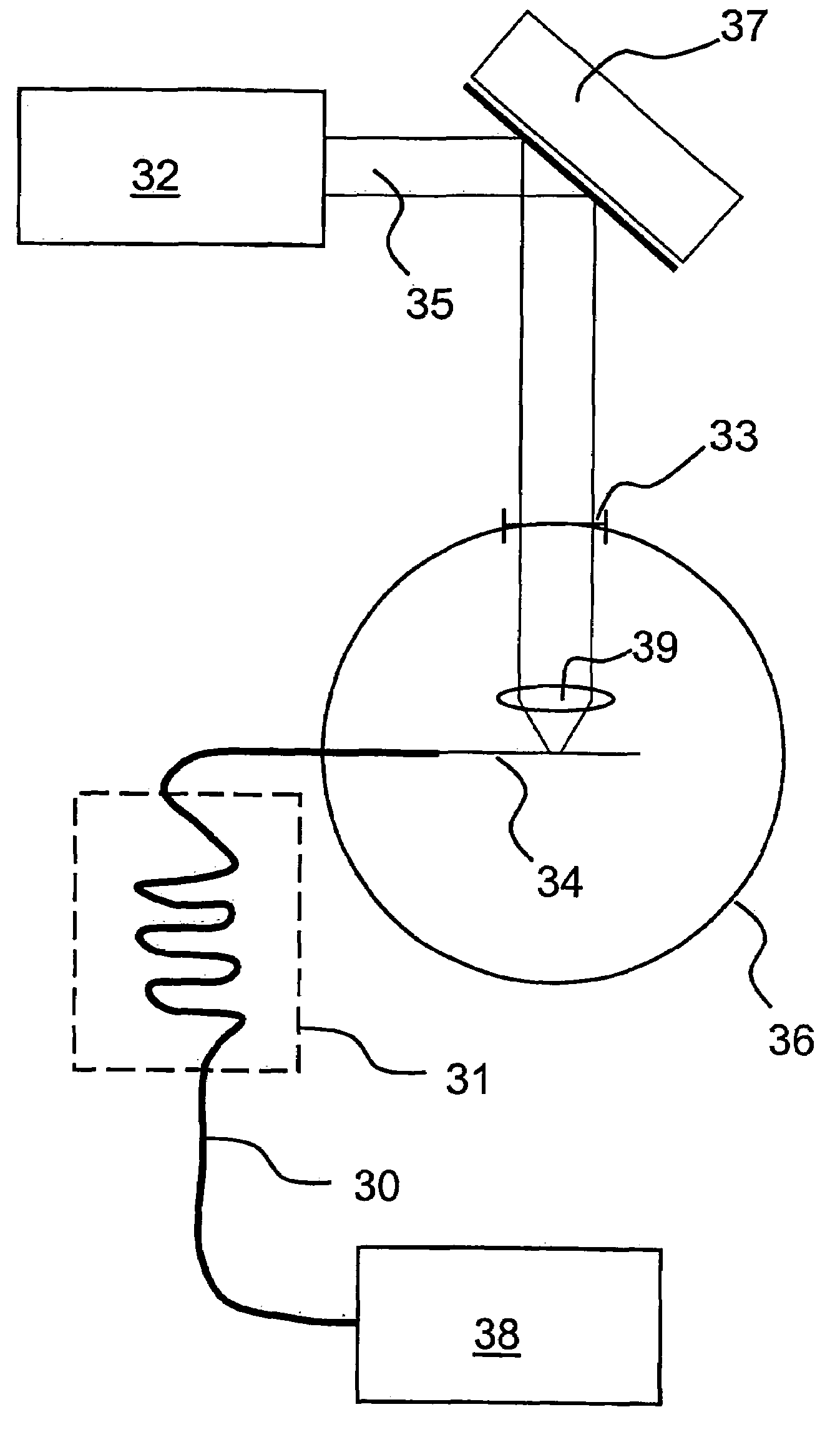
[0047]A first example of an arrangement in which a capillary tubing 30 is employed for supplying target material from a reservoir 38 of target material to a jet-forming orifice (not shown) in the interaction chamber 36 is based upon the advantage of online cooling. According to the present-invention, the container (or reservoir) 38 for target material is located outside the interaction chamber 36. In this particular example, the target material is nitrogen, which is to form a jet of target material in liquid state upon exit from the jet-forming orifice. The capillary tubing 30 is connected at one end to the target material reservoir 38. At the other end of the capillary, an orifice is formed in the manner described above. The capillary 30 has a length of about 50 cm and passes...
PUM
| Property | Measurement | Unit |
|---|---|---|
| length | aaaaa | aaaaa |
| length | aaaaa | aaaaa |
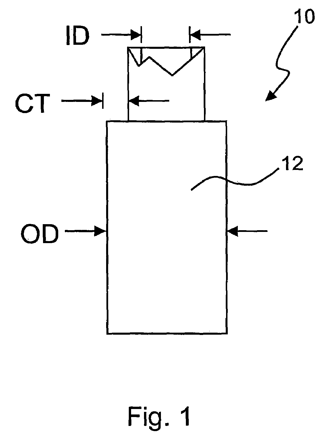
| inner diameter ID | aaaaa | aaaaa |
Abstract
Description
Claims
Application Information