VCSEL fault location apparatus and method

a technology of vertical cavity surface and fault location, which is applied in the direction of measuring devices, testing fibre optics/optical waveguide devices, instruments, etc., can solve the problems of time-consuming and costly use of separate testing apparatus to locate faults within optical fibers, and requires a trained operator

Active Publication Date: 2007-05-15
NAT TECH & ENG SOLUTIONS OF SANDIA LLC
View PDF9 Cites 16 Cited by
  • Summary
  • Abstract
  • Description
  • Claims
  • Application Information

AI Technical Summary

Benefits of technology

[0019]The present invention further relates to an apparatus for locating a fault within a single-mode optical fiber. The apparatus comprises a vertical-cavity surface-emitting laser (VCSEL) which further comprises a quantum-well active region surrounded by a pair of distributed Bragg reflectors, with the VCSEL generating a pulse of light that is coupled into one end of the single-mode optical fiber, and subsequently detecting a portion of the pulse of l...

Problems solved by technology

The use of a separate testing apparatus to locate faults within an o...

Method used


Image

  • VCSEL fault location apparatus and method
  • VCSEL fault location apparatus and method
  • VCSEL fault location apparatus and method

Examples


Embodiment Construction

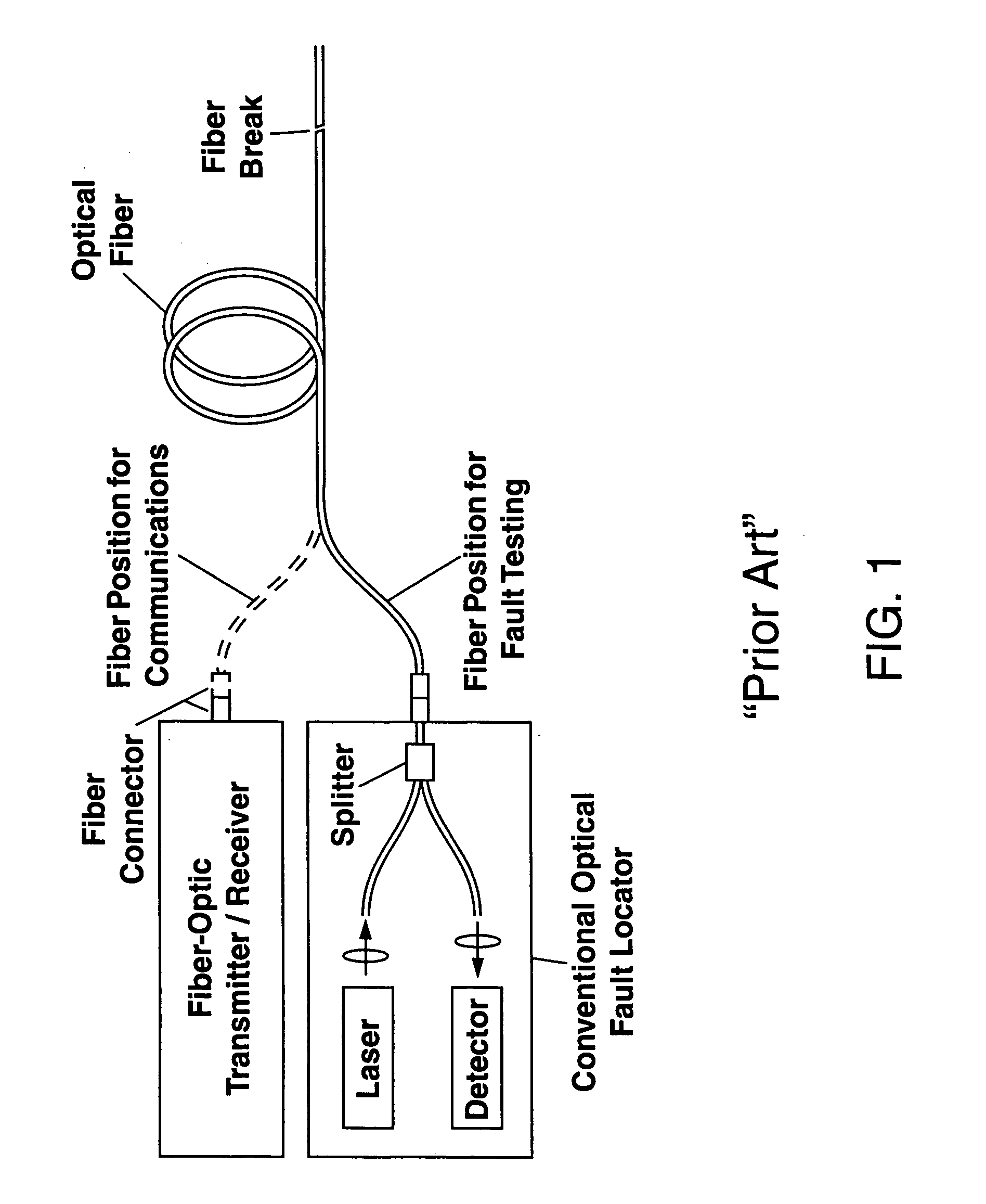
[0029]Referring to FIG. 1, there is shown schematically a conventional optical fault locator which includes a separate laser and light detector. The laser generates a pulse of light (indicated by the horizontal arrow pointing to the right in FIG. 1) which is coupled into an optical fiber to be tested through an optical fiber splitter. Any reflected or backscattered light from a fault within the optical fiber (e.g. the fiber break shown in FIG. 1) is then coupled back into the conventional optical fault locator and directed by the splitter to the separate light detector. The timing between when the pulse of light is generated by the laser and when the reflected or backscattered pulse of light is detected by the detector can then be used in conjunction with a knowledge of the refractive index of the optical fiber to determine the location of the fault within the optical fiber since the distance d to the fault is given by:

[0030]d=c⁢⁢Δ⁢⁢t2⁢⁢n

where c is the speed of light, Δt is a time d...


PUM


Abstract

An apparatus for locating a fault within an optical fiber is disclosed. The apparatus, which can be formed as a part of a fiber-optic transmitter or as a stand-alone instrument, utilizes a vertical-cavity surface-emitting laser (VCSEL) to generate a test pulse of light which is coupled into an optical fiber under test. The VCSEL is subsequently reconfigured by changing a bias voltage thereto and is used as a resonant-cavity photodetector (RCPD) to detect a portion of the test light pulse which is reflected or scattered from any fault within the optical fiber. A time interval Δt between an instant in time when the test light pulse is generated and the time the reflected or scattered portion is detected can then be used to determine the location of the fault within the optical fiber.

Description

GOVERNMENT RIGHTS[0001]This invention was made with Government support under Contract No. DE-AC04-94AL85000 awarded by the U.S. Department of Energy. The Government has certain rights in the invention.FIELD OF THE INVENTION[0002]The present invention relates to fault location in optical fibers and, in particular, to a vertical-cavity surface-emitting laser (VCSEL) fault location apparatus that uses a VCSEL which can be operated as a light emitter at one time and thereafter as a light detector to locate any faults within an optical fiber. The VCSEL fault location apparatus can also be built into a VCSEL fiber-optic transmitter so that the same VCSEL which is used as a transmitter for optical fiber communications can also be reconfigured to determine the presence and location of any faults within the optical fiber.BACKGROUND OF THE INVENTION[0003]In optical fiber communications there is a need to ascertain the location of any faults within an optical fiber so that these faults can be ...

Claims


Application Information

Patent Timeline
IPC IPC(8): G01N21/00
CPCG01M11/3109
Inventor KEELER, GORDON A.SERKLAND, DARWIN K.
Owner NAT TECH & ENG SOLUTIONS OF SANDIA LLC
Why Eureka
Try Eureka