Magnetic recording medium, and thermal stability measuring method and apparatus of magnetic recording medium

a recording medium and magnetic recording technology, applied in the field of magnetic recording media, can solve the problems of attenuation of recorded signals, and disappearance of recorded signals, etc., and achieve the effect of facilitating projection to the environmental tank, accurate measurement and evaluation, and accurate measurement and evaluation

Inactive Publication Date: 2007-05-22
WD MEDIA SINGAPORE PTE
View PDF3 Cites 78 Cited by
  • Summary
  • Abstract
  • Description
  • Claims
  • Application Information

AI Technical Summary

Benefits of technology

[0080]In the present invention, by setting the write track width of the write element of the head to be larger than the total of the track width of the radial direction of the track position on the magnetic layer of the magnetic disk, and the movement amount of the track position in the radial direction by thermal expansion of the support member for supporting the head by the thermal influence, only the signal attenuation by the thermal fluctuation of the magnetic recording medium can accurately be measured and evaluated without being influenced by a thermal off-track.
[0081]Moreover, in the present invention, there is provided a technique of using the head comprising the read/write element in which the write track width is twice or more as large as the read track width. Therefore, only the signal attenuation by the thermal fluctuation of the magnetic recording medium can accurately be measured and evaluated without being influenced by the thermal off-track.
[0082]Furthermore, in addition to the predetermined head, by employing a mechanism in which a head arm as the head support member is mechanically fixed, the magnetic head is fixed/disposed onto the predetermined position

Problems solved by technology

However, if the crystals of the magnetic layer are made very fine for the purpose of the reduction of the noise, magnetization is thermally unstable, and a recorded signal attenuates with time and finally it disappears.
Moreover, when the crystal particle diameter of the magnetic layer becomes very fine so as to reduce the noises, the magnetization becomes thermally unstable, thereby causing a phenomenon in which recorded signals are attenuated with time and finally disappear, that is, a phenomenon called thermal fluctuation.
However, when the film thickness of the seed layer is increased to obtain a high coercive force, the crystal particle diameter and particle diameter distribution forming the seed layer increase, and the crystal particle diameter and particle diameter distrib

Method used


Image

  • Magnetic recording medium, and thermal stability measuring method and apparatus of magnetic recording medium
  • Magnetic recording medium, and thermal stability measuring method and apparatus of magnetic recording medium
  • Magnetic recording medium, and thermal stability measuring method and apparatus of magnetic recording medium

Examples


example 1

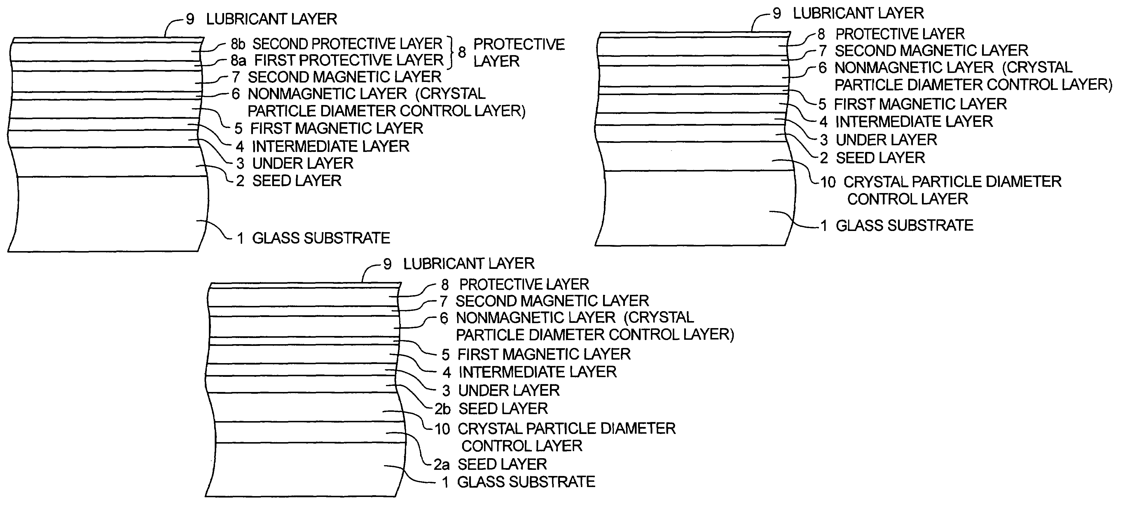
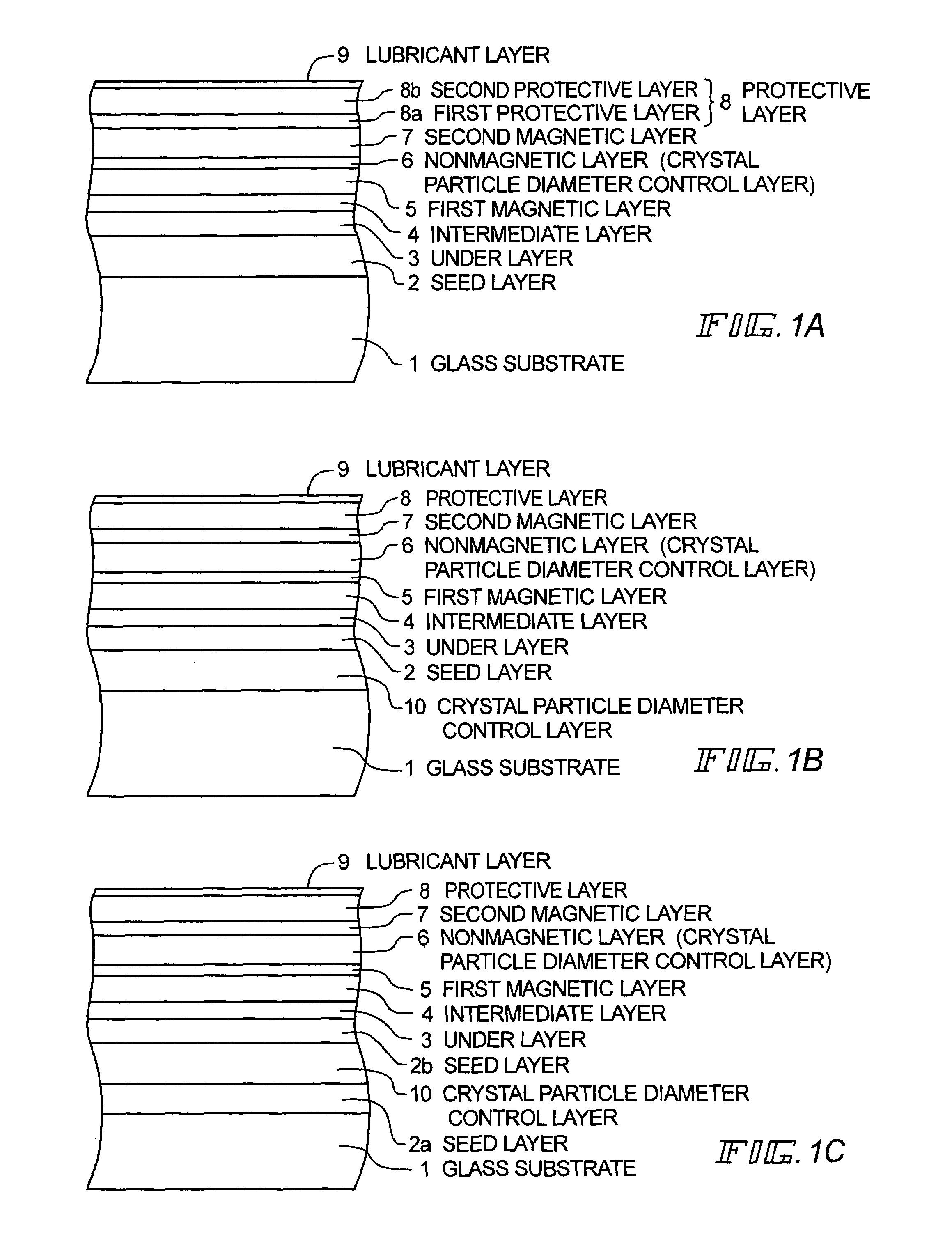
[0099]As shown in FIG. 1, the magnetic recording medium of Example 1 comprises a magnetic disk formed by successively laminating a seed layer 2, an under layer 3, an intermediate layer 4, a first magnetic layer 5, a nonmagnetic layer 6, a second magnetic layer 7, a protective layer 8, and a lubricant layer 9 on a glass substrate 1.

[0100]The glass substrate 1 is formed of a chemically reinforced aluminosilicate glass, and the surface is mirror-polished to provide a surface roughness Rmax=3.2 nm, Ra=0.3 nm. The seed layer 2 comprises an NiAl thin film (film thickness: 700 angstroms). Additionally, this NiAl thin film is constituted at a composition ratio of Ni: 50 at %, Al: 50 at %.

[0101]The under layer 3 is a CrMo thin film (film thickness: 100 angstroms), and is disposed to enhance the crystal structure of the magnetic layer. Additionally, this CrMo thin film is constituted at a composition ratio of Cr: 90 at %, Mo: 10 at %. Moreover, the intermediate layer 4 is a CoCr thin film (fi...

examples 6 to 10

, Comparative Examples 4 to 7

[0124]The magnetic discs were formed in the similar manner as in Example 1, except that the composition of the nonmagnetic layer 6 of CrMn2C0.05 (Cr: 97.95 at %, Mn: 2 at %, C, 0.05 at %) of Example 1 was changed to CrMn0.5C0.01 (Cr: 99.49 at %, Mn: 0.5 at %, C, 0.01 at %) (Example 6), CrMn5C0.01 (Cr: 94.99 at %, Mn: 5 at %, C, 0.01 at %) (Example 7), CrMn2C0.1 (Cr: 97.9 at %, Mn: 2 at %, C: 0.1 at %) (Example 8), CrMn2C0.5 (Cr: 97.5 at %, Mn: 2 at %, C, 0.5 at %) (Example 9), CrC0.2 (Cr: 99.8 at %, C, 0.2 at %) (Example 10), CrMn2 (Cr: 98 at %, Mn: 2 at %) (Comparative Example 4), CrMn2C0.55 (Cr: 97.45 at %, Mn: 2 at %, C, 0.55 at %) (Comparative Example 5), CrMn0.4C0.01 (Cr: 99.59 at %, Mn: 0.4 at %, C, 0.01 at %) (Comparative Example 6), and CrMn6C0.01 (Cr: 93.99 at %, Mn: 6 at %, C, 0.01 at %) (Comparative Example 7). The coercive force, S / N ratio, and PW50 of these magnetic disks are as shown in a table of FIG. 3.

examples 11 to 13

[0125]The magnetic recording media were formed in the similar manner as in Example 1, except that the nonmagnetic layer (crystal particle diameter control layer) of CrMnCN (layer thickness: 500 Å) of Example 1 was formed between the substrate and the seed layer (Example 11, FIG. 1B), the seed layer was constituted of two layers and the nonmagnetic layer (crystal particle diameter control layer) of CrMnC (layer thickness: 15 Å) of Example 1 was formed between the seed layers (Example 12, FIG. 1C), and 15 at % of Mo was added to the material (Mn: 2 at %, C, 0.05 at %, Mo: 15 at %, Cr: residue) of the nonmagnetic layer (crystal particle diameter control layer) of Example 1 (Example 13). The nonmagnetic layer constituted of CrMnCN was formed in an atmosphere of Ar+N2(N2:20 at %) mixture gases by in-line sputtering.

[0126]In the magnetic recording medium of Example 11, by further disposing the CrMnC layer under the seed layer, the crystal orientation properties of the magnetic layer (Co) ...


PUM


Abstract

There is disclosed a magnetic recording medium in which a seed layer, under layer, intermediate layer, first magnetic layer, nonmagnetic layer, second magnetic layer, protective layer, and lubricant layer are successively laminated on a glass substrate, the nonmagnetic layer is constituted of an alloy containing Cr and C, and the magnetic layer is constituted of an alloy containing Co and Pt. The under layer includes at least the seed layer for finely dividing the crystal particles of the magnetic layer, the seed layer includes at least two or more layers of nonmagnetic films, and the intermediate layer formed of the material different from that of the nonmagnetic film is interposed between the nonmagnetic films. In measurement of the thermal stability of the magnetic recording medium, a head is used, the head includes a read/write element, and a write track width is twice or more as large as a read track width in the head.

Description

[0001]This application claims Paris Convention priority right based on Japanese patent applications Hei 11-94386, Hei 11-94391 and Hei 11-93905, filed Mar. 31, 1999, the entire disclosure of which is incorporated herein by reference.BACKGROUND OF THE INVENTION[0002]1. Field of the Invention[0003]The present invention relates to magnetic recording media such as a hard disk mounted on a computer, and the like, particularly to a magnetic recording medium which has a high coercive force and which inhibits the generation of noises during regeneration of a recording signal.[0004]The present invention also relates to a method and apparatus for accurately measuring and evaluating a signal decay by the thermal fluctuation of a magnetic recording medium in a simple method before the magnetic recording medium is incorporated into a magnetic storage apparatus.[0005]2. Description of the Related Arts[0006]As this kind of magnetic recording medium, for example, such a magnetic recording medium as...

Claims


Application Information

Patent Timeline
IPC IPC(8): G11B5/66G11B5/70G01R33/12G11B5/012G11B5/40G11B5/455G11B5/73G11B5/738
CPCG11B5/455G11B5/66G11B5/732G11B5/7325G11B5/40G11B5/7379G11B5/73921G11B5/7369
Inventor TOMIYASU, HIROSHIUMEZAWA, TEIICHIROHATA, GENSHICHIMORIKAWA, TAKASHIKOBAYASHI, MASATOSUZUKI, MASASHIYOKOTA, SATOSHIWATANABE, TSUYOSHI
Owner WD MEDIA SINGAPORE PTE
Why Eureka
Try Eureka