Optical apparatus

a technology of optical apparatus and optical characteristics, applied in the field of optical apparatus, can solve the problems of difficult analysis of particle or object as a whole, difficulty in measuring optical characteristics of particles, and difficulties in flow cytometry, so as to increase the transmission efficiency of optical apparatus and reduce length

Inactive Publication Date: 2007-05-22
XY
View PDF344 Cites 87 Cited by
  • Summary
  • Abstract
  • Description
  • Claims
  • Application Information

AI Technical Summary

Benefits of technology

[0031]Suitably the prisms are manufactured from optical glass such as BK7 optical glass. However, where the application is intended for use with UV electromagnetic radiation, it is preferred to manufacture the prism from UV-suitable material such as fused silica. In such an application, it is also desirable that the reflective surface be comprised of a UV-grade mirror to increase the transmission efficiency of the optical apparatus.

Problems solved by technology

Where the particle or object is asymmetrical, the light measurements will vary depending on which portion is illuminated, making it difficult to analyze the particle or object as a whole.
Such difficulties are encountered in flow cytometry since it is common for particles being analyzed to be asymmetrical e.g. mammalian spermatozoa.
One problem with conventional flow cytometers is that particle asymmetry often renders the optical characteristics of a particle difficult to measure.
Thus, particle asymmetry can lead to a reduced resolution of measurement of the particles.
It follows that, in cytometers with a sorting capability, this reduced resolution in measurement of the particles results in a decreased ability to accurately separate populations of cells with different optical properties.
Such a problem is encountered in separation of male and female mammalian sperm.
Utilizing such a technique in artificial breeding would offer considerable economic advantages in livestock management, but is currently made difficult by the asymmetric geometry of the flat sperm head.
However, this system still had a number of drawbacks.
One drawback was that it was a requirement for this system that the sample flow be moving slowly with respect to the sheath flow, thereby reducing sample throughput.
A further drawback was that it only produces good alignment at very low flow rates.
It will be appreciated that the rejection of unaligned cells again reduces the processing rate of this system and unnecessarily wastes sperm cells.
A further problem with this system is that it is unable to provide a particle sort function (i.e. according to sperm sex).
While this system also demonstrated a good ability to eliminate the orientation dependencies of bull sperm, it was also incapable of modification for high speed sorting.
Unfortunately, such laser systems can be quite expensive and only add to the cost of devices such as flow cytometers.
Because lasers typically deliver a single wavelength of light, use of lasers also has made it difficult to utilize a single light source to provide a variety of wavelengths of light, e.g. in conjunction with filters that filter out all but the desired wavelengths.
This can be a tedious process that adds to the expense of the analyzation instruments.

Method used


Image

  • Optical apparatus
  • Optical apparatus
  • Optical apparatus

Examples


Embodiment Construction

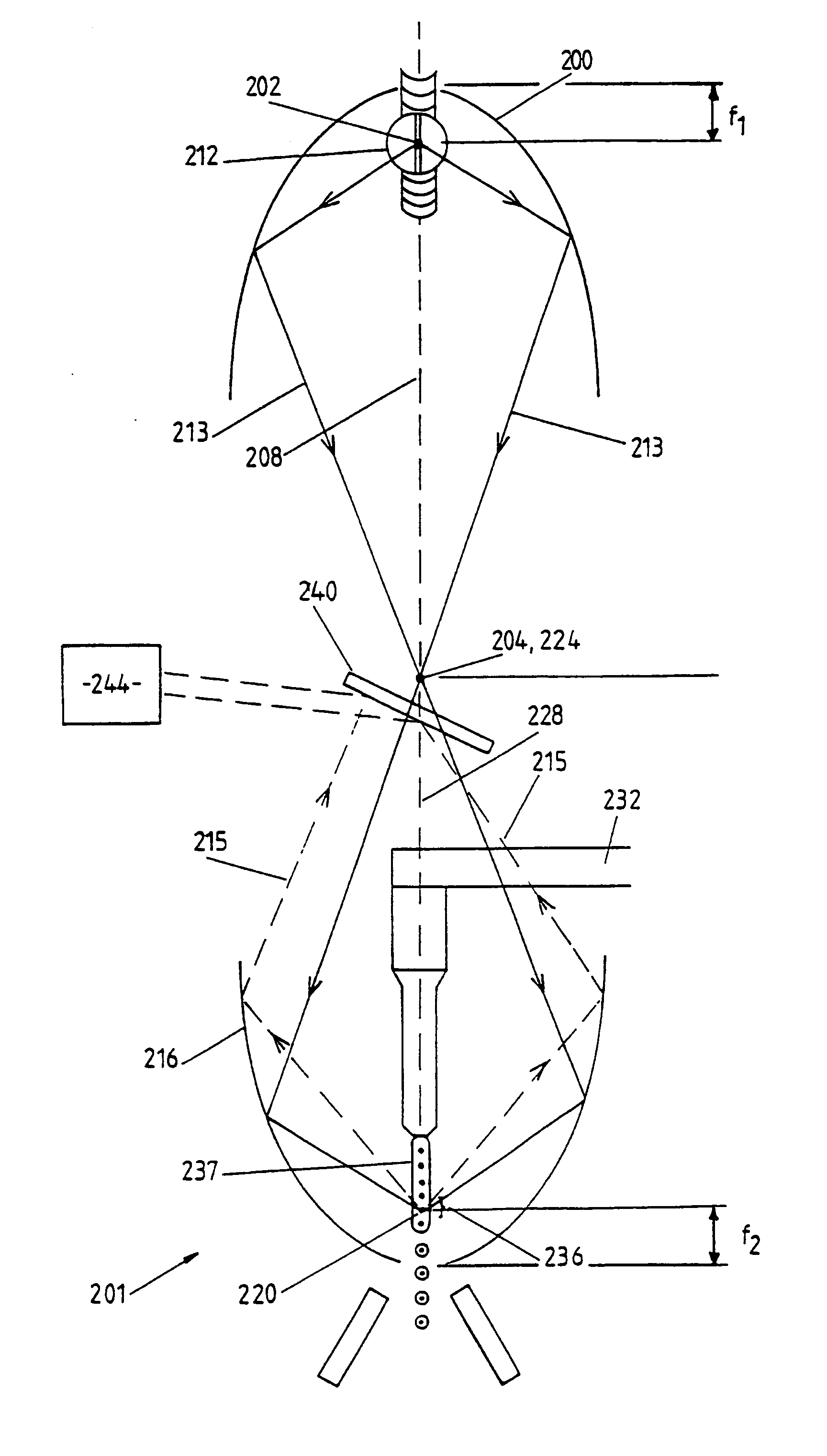
[0093]Some embodiments of the invention are discussed in “A New Optical Configuration for Flow Cytometric Sorting of Aspherical Cells”, Int. Soc. Optical Engr., Proc. Of Adv. Tech. Analytical Cytology, 1997, by John C. Sharpe, Peter N. Schaare and Rainer Kunnemeyer; “Radially Symmetric Excitation and Collection Optics for Flow Cytometric Sorting of Aspherical Cells”, Cytometry 29:363–370 (1997) by John C. Sharpe, Peter N. Schaare, and Rainer Kunnemeyer; and “A New Optical Configuration for Flow Cytometric Sorting of Bovine Spermatozoa by Sex”, a thesis submitted to the University of Waikato for the degree of Doctor of Philosophy in Physics by Johnathan Charles Sharpe, which are hereby incorporated by reference.

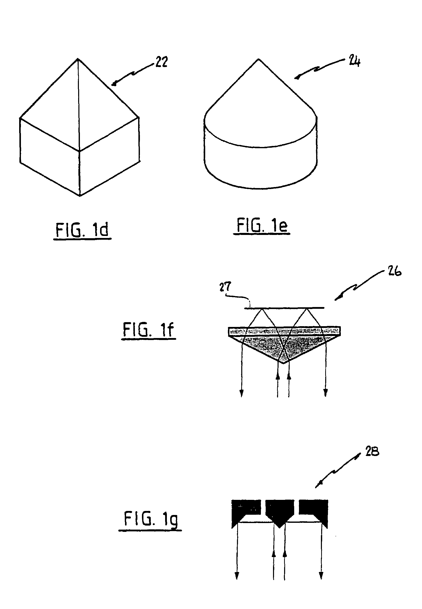
[0094]FIG. 1(a) illustrates an optical apparatus including a prism 1. The prism 1 has an apex 2 at a forward end of the prism, a right conical portion having a conical face 2, and a right cylindrical base portion contiguous with the conical portion. The base portion has a circ...


PUM

PropertyMeasurementUnit
anglesaaaaaaaaaa
anglesaaaaaaaaaa
angleaaaaaaaaaa

Abstract

Various optical apparatus provide a source of parallel light (7, 75). The parallel light (7, 75) is generally achieved by directing an incident beam at the apex of a prism (1, 22, 24, 26, 28). The prism may have varying configurations. One configuration has a forward conical face (24). Another configuration has a pyramidal forward end (22). Other configurations are also disclosed. The application also discloses the use of reflectors (20, 78, 216, 316, 400) having internal reflective surfaces shaped as three-dimensional figures of revolution, for example paraboloid or ellipsoid. The reflectors (20, 78, 216, 316) focus light incident onto the reflectors at one or more foci (F, 220, 320, 420). The reflectors may be used in combination with the optical apparatus including the prisms (1, 22, 24, 26, 28). The reflectors (20, 78, 216,316) may be used in flow cytometers for focusing light at a sample stream (237, 337) passing through the focus (F, 220, 320, 420) of the reflector (20, 78, 216, 316). The collection of scattered and / or fluorescent light from an illuminated sample stream (237, 337) in a flow cytometer may be achieved with the use of a collector shaped as a figure of revolution e.g. paraboloid or ellipsoid. Various optical methods and methods for flow cytometry are also disclosed.

Description

CROSS-REFERENCES TO RELATED APPLICATIONS[0001]This application is a continuation application of, and claims the benefit and priority of, U.S. patent application Ser. No. 09 / 355,461, filed Sep. 17, 1999, issuing Nov. 16, 2004 as U.S. Pat. No. 6,819,411, which was a United States National Phase patent application of International Application No. PCT / NZ98 / 00009, published Aug. 6, 1998, filed Feb. 2, 1998, which claims the benefit of and priority from New Zealand Provisional Specification Number 314169 filed Jan. 31, 1997, each above-mentioned application hereby incorporated by reference.TECHNICAL FIELD[0002]This invention relates to an optical apparatus. In particular, although not exclusively, this invention has application to the field of flow cytometry. However, it is to be understood that several of the inventive aspects have application beyond flow cytometry and may have broad application in the field of optics generally. For example, several aspects of the invention may be used i...

Claims


Application Information

Patent Timeline
Patent Type & Authority Patents(United States)
IPC IPC(8): G01N21/00G01N33/48G01N15/02G01N15/14G01N21/47G02B5/00G02B5/04G02B27/09
CPCG01N15/1436G01N21/49G02B5/04G01N15/1434G01N15/1459G01N2015/149G01N2021/6469G01N2015/1452
Inventor SHARPE, JONATHAN C.SCHAARE, PETER N.
Owner XY
Why Eureka
Try Eureka