System for a portable hands-free breast pump and method of using the same

a breast pump and hands-free technology, applied in the field of hands-free, visually friendly, portable, breast pump system, can solve the problems of electric pumps that may be self-cycling or require some manual user control, are cumbersome and difficult to use, and are typically uncomfortable, so as to facilitate the numerous benefits of breast-feeding, reduce the contamination of milk, and accurately emulate the suckling action of a baby.

Active Publication Date: 2007-05-29
MEDELA HLDG AG
View PDF18 Cites 104 Cited by
  • Summary
  • Abstract
  • Description
  • Claims
  • Application Information

AI Technical Summary

Benefits of technology

[0015]It is still another purpose of this invention to reduce the contamination of the milk during the processing, such as collection and storage, by a breast pump system.
[0016]It is still ano

Problems solved by technology

Further, the electric pumps may be self-cycling or require some manual user control.
While most hand pumps are inexpensive and portable, they are typically uncomfortable, inefficient, and difficult to clean.
Other electric pumps, such as the diaphragm pump disclosed in U.S. Pat. Nos. 6,257,847 and 6,090,065, are assembled from many parts (hoses, gaskets, valves, etc.) which are difficult to clean, wash and carry. FIG. 27 illustrates such a prior art system from the '065 patent having many parts which makes it cumbersome and difficult to use.
Most of the electric breast pumps, such as Hollister's Purely Yours™ Kit, are cumbe

Method used


Image

  • System for a portable hands-free breast pump and method of using the same
  • System for a portable hands-free breast pump and method of using the same
  • System for a portable hands-free breast pump and method of using the same

Examples


second embodiment

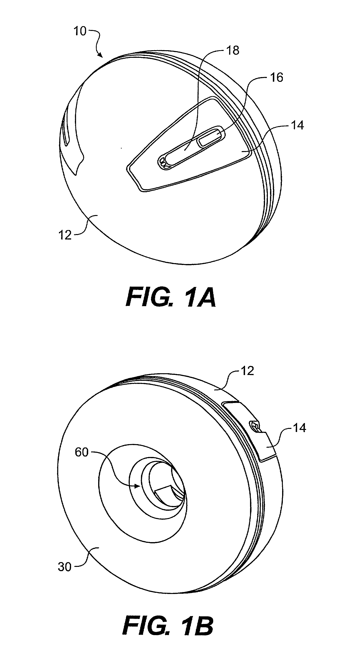
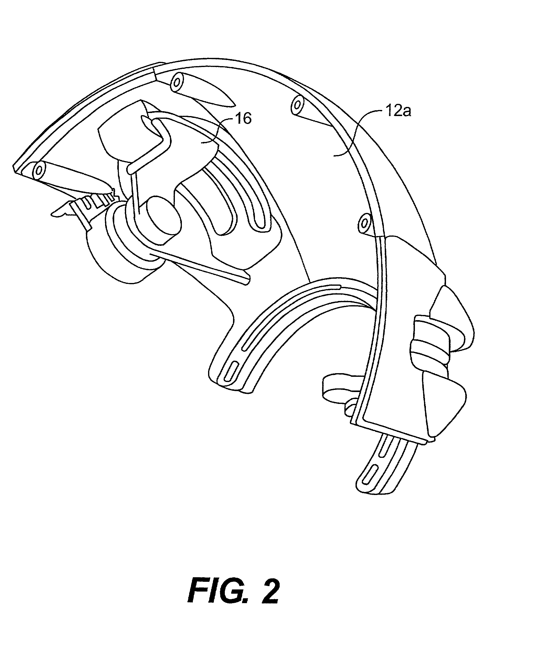
[0047]In a second embodiment shown in FIG. 3, the slide button 16 is configured to slide in a circumferential direction along the groove 18 so as to adjust the pumping action to continuously vary the vacuum level. A push button 20 is used to control the cycling rate by incrementally increasing the rate with each push of the button 20 up to the fastest cycling rate designed into the pump. A further push of the button 20 then rolls the increment back to the slowest cycling rate for a continuous loop operation. FIG. 4 depicts that the slide button 16 is connected to an electrical contacting base 21 with an arm 16a so as to slide the electrical contacting base 21 and vary the vacuum level.

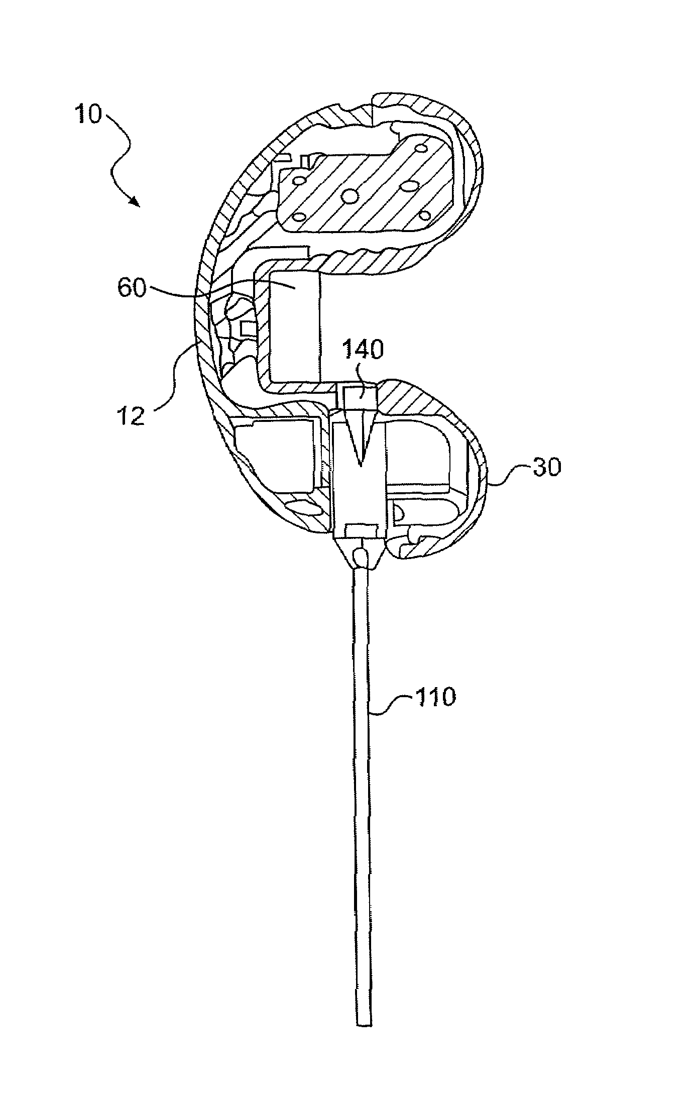
[0048]Referring to FIG. 5, each breast pump 10 includes a housing shell 12, a central deck 22 with a servomotor mechanism 24 integrated therewith, and a straw-hat shaped breast “flange”30 having a flange top 35. The servomotor mechanism 24 is a servomotor mechanism powered by at least one power source ...

third embodiment

[0054]In the breast pump, power for the external servomotor mechanism 24 is located outside the housing. As shown in FIG. 8A, an adapter 46 is used to connect a positive contacting pin to the external power supply 26 via a wire 26a. FIG. 9 shows an inset view of how the adapter 46 is attached to the positive contacting pin 44. This embodiment has the advantage of a longer-lasting power supply that can be used, for example, in an institutional setting (i.e., a hospital) or even a home setting where a more limited range of mobility is acceptable or even desired.

[0055]Alternatively, as shown in FIG. 8B, the servomotor mechanism 24 may be replaced by a servomechanism 24′ that may be just a mechanical or pneumatic linkage 101 connected to the lever arm 21 for implementing the pumping action of the vacuum chamber 60. The linkage 101 is connected to a remote control 103 that acts as the user's control for pumping via a linkage element 103. For example, in a mechanical implementation, the l...

first embodiment

[0063]In the rear-piston lever-arm system 100, as shown in the exploded view of FIG. 11A, the top of the piston cylinder 25 is shaped like a yo-yo or a doughnut without a hole. The lever arm 21 has a protrusion 21a on the top that contacts with the alignment dome 25b of the piston cylinder 25. The lever arm 21 is a projecting handle used to adjust or operate the piston cylinder 25. In particular, the-rear piston lever-arm system 100 mechanically communicates with the servomotor mechanism 24 so as to be activated by the mechanism and thereby pivotally move the lever arm 21 which then linearly moves the piston cylinder 25 along a line generally parallel with the centerline of the pump 10. Such a linear movement is depicted, wherein the start or “upstroke” position of the piston cylinder's linear movement is shown in FIG. 11B.

[0064]FIG. 11C shows the lever arm 21 pivoted forward thereby linearly pushing the piston cylinder toward the flange 30 in a “downstroke” motion. The lever arm 21...


PUM

PropertyMeasurementUnit
Pressureaaaaaaaaaa
Lengthaaaaaaaaaa
Shapeaaaaaaaaaa

Abstract

A portable, hands-free and user friendly breast pump for facilitating breast-feeding, incorporates a dome-shaped housing having a servomotor mechanism; a hat-shaped flange having a chamber portion, a brim portion and an outlet, the chamber portion being formed so as to be placed over a nipple on a breast so as to define a chamber between the flange and the breast, and the brim portion being formed to surround the nipple and thereby form a suction seal therebetween; and a one-way venting element formed to operatively communicate with the chamber so as to vent pumped milk from the chamber via the outlet. The housing, the flange and the venting element are connected into an integral device held against the breast and underneath clothing so as to keep the integral device hidden. Breast milk is collected via a plastic collection bag that connects directly with the pump underneath clothing such that the milk is isolated from any contaminants in the air and may be easily stored immediately after being collected.

Description

BACKGROUND OF THE INVENTION[0001]1. Field of the Invention[0002]The invention generally relates to a portable, hands-free, and visually friendly breast pump system and method for collecting milk from a breast of a nursing mother which may be hidden from view when in use. In particular, the invention may be hidden underneath the clothing of a nursing mother, which provides privacy and avoids any attention and the awkwardness experienced by the nursing mother using existing breast pumps.[0003]2. Description of the Related Art[0004]Breastfeeding is the best source of nutrition for a baby, and it also offers health benefits to the nursing mother. Often, the nursing mother needs to use a breast pump to collect milk. A variety of breast pumps are available. The basic types of breast pumps include manual (hand operated) pumps and electric pumps. The electric pumps may be battery and / or AC powered. Further, the electric pumps may be self-cycling or require some manual user control. U.S. Pat...

Claims


Application Information

Patent Timeline
IPC IPC(8): A61M1/06
CPCA61M1/06A61M1/064A61M2209/088A61M2205/8206A61M1/062A61M1/067A61M1/0697A61M1/06935
Inventor MYERS, KENNETH E.LUNDY, ELLENMEINCKE, DREW F.BIRDSEYE, SHARON
Owner MEDELA HLDG AG
Why Eureka
Try Eureka