
Method for making memory cards and similar devices using isotropic thermoset materials with high quality exterior surfaces

a technology of isotropic thermoset materials and memory cards, which is applied in the direction of coatings, printed circuit boards, instruments, etc., can solve the problems of reducing the size and number of electronic components, limiting the positioning options of electronic components, and damaging microchips and other small electronic components. , to achieve the effect of saving processing time, reducing manufacturing cycle time, and high quality

Inactive Publication Date: 2007-06-05
CARDXX
View PDF24 Cites 252 Cited by
  • Summary
  • Abstract
  • Description
  • Claims
  • Application Information

AI Technical Summary

Benefits of technology

"This patent describes a new type of memory card that is very thin and secure. The card contains securely encapsulated electronics and has high-quality surfaces for printing graphics. The process of making the memory card is efficient and uses less energy, resulting in faster production times. The card can also have multiple electronic components on it, and the process allows for the production of inlays, which are the components of the memory card. Overall, this patent provides a way to make thin, secure, and efficient memory cards with improved production efficiency."

Problems solved by technology

The high-pressure injection and high temperature can damage a microchip and other small electronic components, particularly wire bonds.
This is a particular problem in the prior art processes because the injection occurs under the influence of rather high pressures.
The use of such holding devices can limit the positioning options for the electronic components in the memory card.
The positioning limitation also may cut down on the size and number of electronic components that can be placed in such memory cards.
This limitation in turn limits the amount of memory that can be put into an MMC.
Additionally, due to differences in the coefficients of expansion of the materials used to make these relatively large holding devices—relative to the coefficient of expansion of the other elements of such cards—deformations often appear on the external surfaces of finished cards that contain such electronic component holding devices.
That is to say that surface deformations can result from the mere presence of such holding members in the body of the card as it experiences different temperatures and pressures during its manufacture.
Such deformations are, at best, unsightly; at worst, they may prevent the card from lying completely flat in the card-receiving receptacles in certain card reading machines.
The use of glues to secure electronic components has, however, resulted in another set of problems.
These problems are due to the fact that most commercially available, fast-curing glues that are used to fix such electronic components in place are often characterized by their high degree of shrinkage.
Moreover, relatively large volumes of glue are needed to fix the electronic components.
Use of relatively large volumes of high-shrinkage glue tend to wrinkle and otherwise deform the region of the plastic sheet or layer to which such glues are applied.
Beyond certain tolerances, these wave-like bends are unacceptable in the memory card industry because a deformed memory card will be inoperable in certain devices.
One additional limitation, which was touched on above, in the manufacture of prior art memory cards is that they are typically produced with prior art processes that involve the injection of filled epoxy resin or high-temperature, high-pressure thermoplastic injection into molded forms.
In addition to the fact that a high-pressure, high-temperature injected material may stress or damage the electronic components of the card, it also takes a relatively long time to set and cool in the mold.
Epoxy resins undergo a chemical reaction following injection, which can damage the electronic components of the memory card.

Method used


Image

  • Method for making memory cards and similar devices using isotropic thermoset materials with high quality exterior surfaces
  • Method for making memory cards and similar devices using isotropic thermoset materials with high quality exterior surfaces
  • Method for making memory cards and similar devices using isotropic thermoset materials with high quality exterior surfaces

Examples


Embodiment Construction

[0023]FIGS. 4(a) and 4(b) illustrate a problem involved with the prior art methods of making Memory Cards. FIG. 4(a) depicts, in cut-away cross section, a sheet or layer of a plastic material 40 (e.g., a sheet or layer of polyvinyl chloride, polyurethane, etc.) having a top surface 41 and a bottom surface 42. Such sheets will generally have a thickness 43 ranging from about 0.075 mm to about 0.25 mm. A mound, drop, or dollop of a liquid or semi-liquid, high shrinkage, glue 44 is depicted as being recently dispensed on the top surface 41 of the plastic sheet 40 shown in FIG. 4(a). The mound of recently dispensed glue 44 depicted in FIG. 4(a) is shown having an initial width W1. FIG. 4(b) shows (in exaggerated form) the results of curing the mound of glue 44 shown in FIG. 4(b) to a smaller mound of cured glue 44′. The width W2 of the mound of cured glue 44′ depicted in FIG. 4(b) is considerably less than the width W1 of the mound of the newly laid liquid or semi-liquid glue 44 in FIG....


PUM

PropertyMeasurementUnit
shrinkageaaaaaaaaaa
shrinkageaaaaaaaaaa
pressureaaaaaaaaaa

Abstract

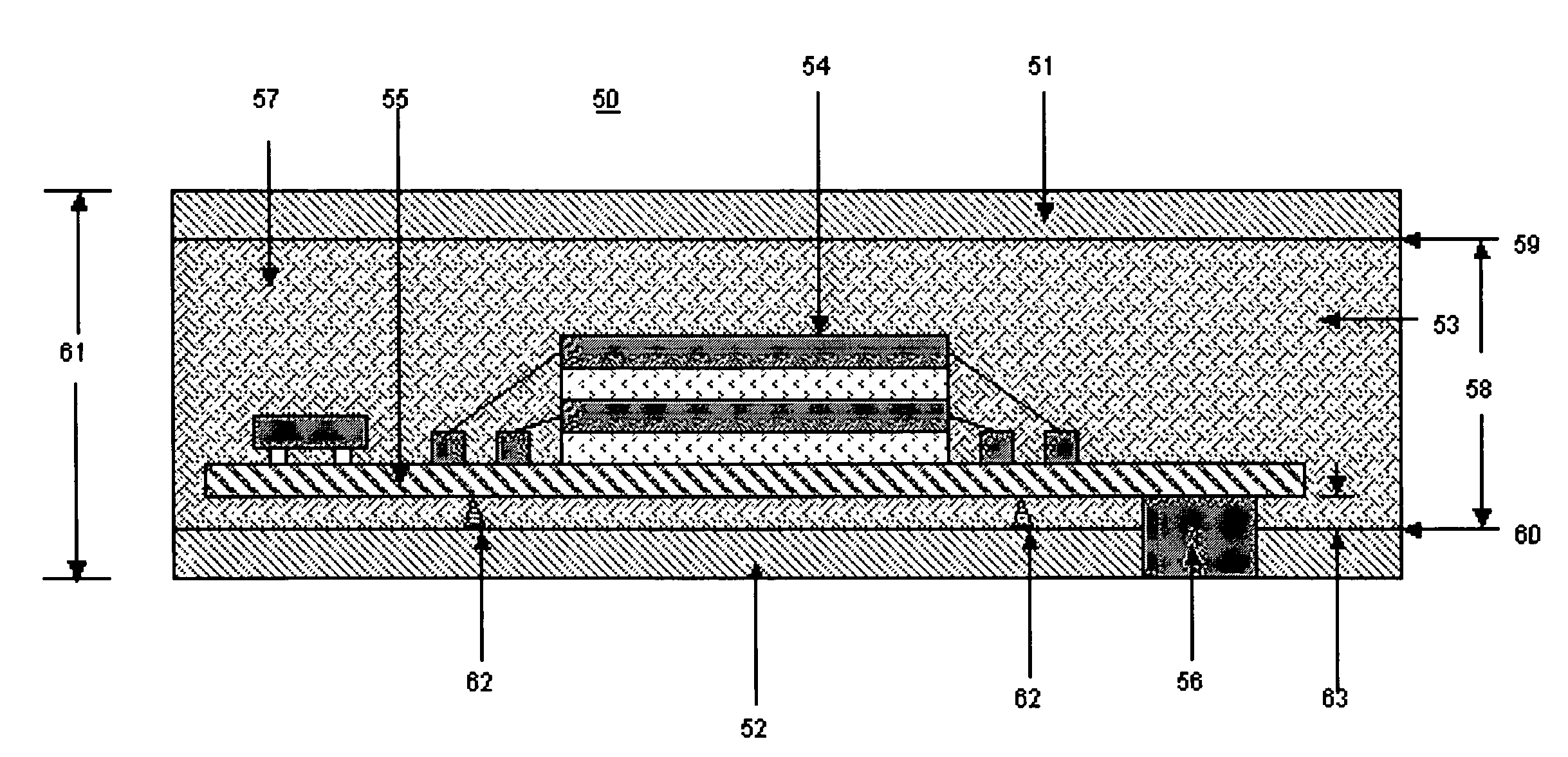
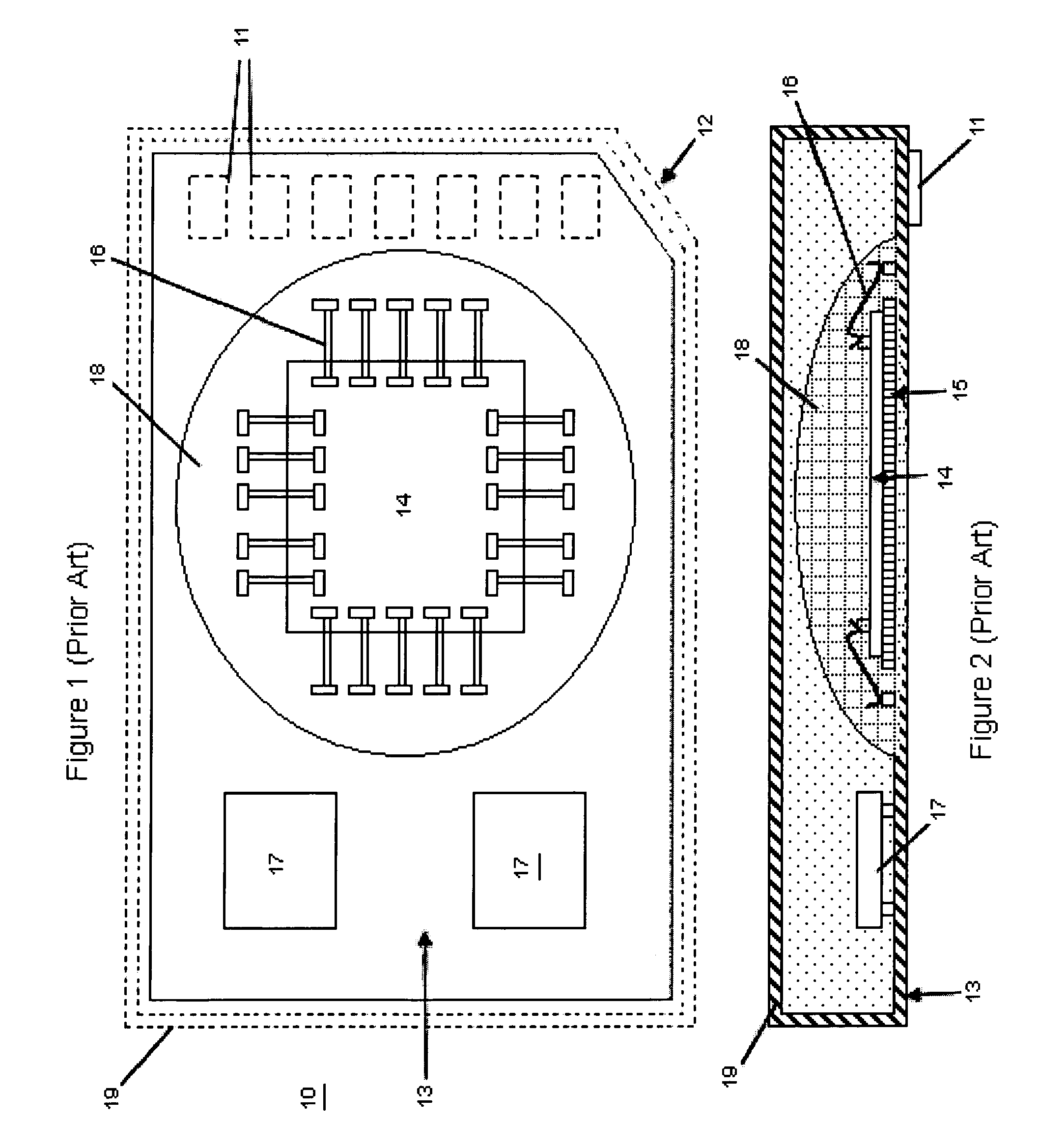
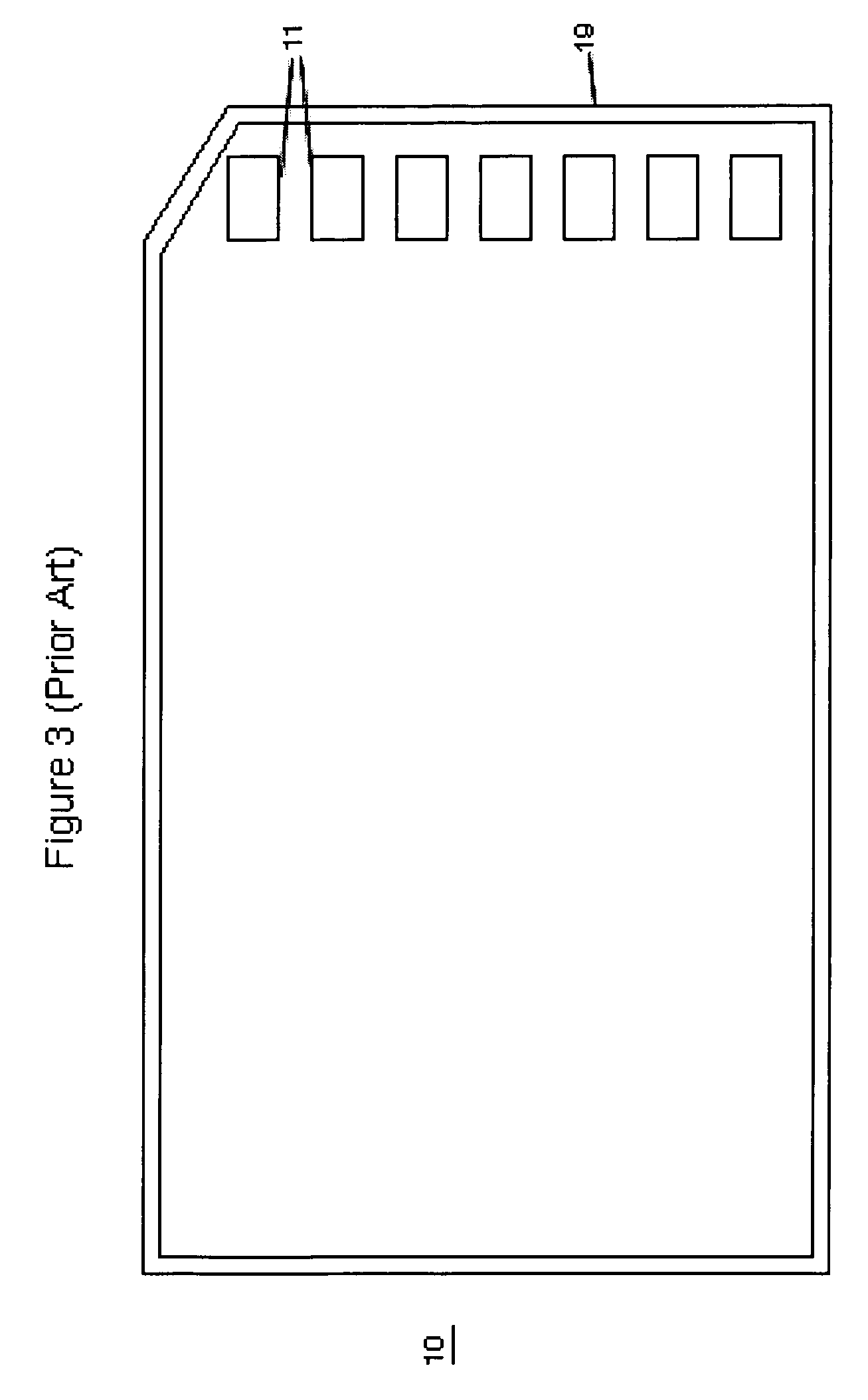
Memory Cards containing Integrated Circuits and other electronic components (e.g. resistors) in a variety of form factors having high quality external surfaces of polycarbonate, synthetic paper (e.g. Teslin), or other suitable material (e.g. PVC) can be made through use of injection molded thermoplastic material or thermosetting material that becomes the core layer of said Memory Cards and similar devices. The object of the invention is to provide the following properties to Memory Cards: rapid production cycle, high volume manufacturing throughput, security, electronics protection, better tamper resistance, durability, and highly reliable complex electronics encapsulation, achieved through a process utilizing low temperature and low pressure.

Description

BACKGROUND OF THE INVENTION[0001]In recent years, consumer electronic devices such as digital cameras, Personal Digital Assistants (PDAs), smart phones, and digital audio and video recorders have driven a strong market demand for removable data storage components. The electronics industry has responded to this demand with products known generically as “memory cards.” A memory card usually contains one or more semiconductor memory chips within an industry-standard housing with dimensions that allow it to be used in conjunction with different devices from various manufacturers. Memory cards typically also have connectors on an external surface that allow electrical connections to the circuitry of consumer electronic devices. Examples of types of memory cards include PC Cards, MultiMedia Cards, CompactFlash Cards, and Secure Digital Cards. These devices are made in accordance with standards promulgated by trade associations such as the Personal Computer Memory Card International Associ...

Claims


Application Information

Patent Timeline
Patent Type & Authority Patents(United States)
IPC IPC(8): H05K3/30
CPCH01L21/565H01L23/3135H05K3/284B29C45/14647B29C45/14467Y10T29/49176B29C2045/14532B29K2027/06B29K2063/00B29K2075/00H01L2224/16H01L2224/48472H01L2224/49175H01L2924/14H05K1/117H05K3/0058H05K3/386H05K3/4007H05K2203/063H05K2203/1316H01L24/48H01L24/49Y10T29/49121Y10T29/49172Y10T29/49146H01L2924/00H01L2924/181H01L2224/05553H01L2924/00014H01L2924/00012H01L2224/45099H01L2224/45015H01L2924/207G06K19/077G06K19/07H05K13/00
Inventor REED, PAUL
Owner CARDXX
Learn More