Surface light source device and light guide used therefor

a light source and surface technology, applied in the direction of planar/plate-like light guides, lighting and heating apparatus, instruments, etc., can solve the problems of uneven brightness distribution of luminance in observation directions, disproportionate brightness, and easy drop of luminance in these portions or regions, so as to reduce power consumption, eliminate various brightness unevenness, and high quality level

Inactive Publication Date: 2007-06-05
MITSUBISHI CHEM CORP
View PDF19 Cites 30 Cited by
  • Summary
  • Abstract
  • Description
  • Claims
  • Application Information

AI Technical Summary

Benefits of technology

[0012]An object of the present invention is to eliminate various brightness unevenness caused by use of the small number of point primary light sources for reduction of power consumption of the above-described surface light source device and to provide a surface light source device having a high quality level.
[0024]In an aspect of the present invention, the light incident end surface is constituted of an anisotropic rough surface, and an average inclination angle of the anisotropic rough surface in a direction along the light outputting surface is larger than that in a direction perpendicular to the light outputting surface. In an aspect of the present invention, in the anisotropic rough surface, the average inclination angle in the direction along the light outputting surface is 3° to 30°, and the average inclination angle in the direction perpendicular to the light outputting surface is 5° or less. In an aspect of the present invention, in the anisotropic rough surface, a length of a region having an inclination angle of 8° or more with respect to an anisotropic rough surface forming surface in measurement in a direction perpendicular to the light outputting surface is 5% or less of a total measured length. In an aspect of the present invention, in the anisotropic rough surface, the surface of an elongated lens extending in a direction perpendicular to the light outputting surface is roughened.

Problems solved by technology

This backlight has a problem that a sufficient quantity of light does not reach light guide corner portions in the vicinity of opposite end portions of the linear or rod-shaped primary light source, or regions of the light guide in the vicinity of side end surfaces of the light guide adjacent to the light incident end surface, and luminance easily drops in these portions or regions.
This brings about disproportionateness (i.e., brightness unevenness) of the luminance distribution of an observation direction in a light emitting surface of the surface light source device.
Thus, it has been difficult to establish both the reduction of the power consumption and maintenance of the uniformity of the luminance distribution in the conventional backlight using the point light source as the primary light source.
Further as a method of eliminating the dark part in the vicinity of an incidence surface in the backlight using a linear light source such as a cold cathode tube as the primary light source, for example, in JP(A)-9-160035, a method of roughening the light incident end surface of the light guide has been proposed, but the above-described dark part cannot be sufficiently eliminated in the backlight using the point light source like the LED as the primary light source in this method.

Method used


Image

  • Surface light source device and light guide used therefor
  • Surface light source device and light guide used therefor
  • Surface light source device and light guide used therefor

Examples


examples

[0161]Examples and comparative examples of the present invention will be described. It is to be noted that in the examples and comparative examples, to measure a micro region inclination angle of a light guide cross-sectional shape, a replica of a elongated lens forming surface of a light guide was prepared, the replica was cut by the surface perpendicular to an extending direction of a elongated lens, and the measurement was performed based on a cross-sectional shape line obtained by enlargement of a cut end surface with an optical microscope, electron microscope or another image pickup means. Calculation of a histogram or degree distribution of an absolute value of the micro region inclination angle, and calculation of a valley portion inclination angle were performed in the same manner as described above with reference to FIGS. 6A and 6B. Additionally, when the cross-sectional shape was equally divided to set the micro regions as described above, the measuring of a coordinate of ...

example 1

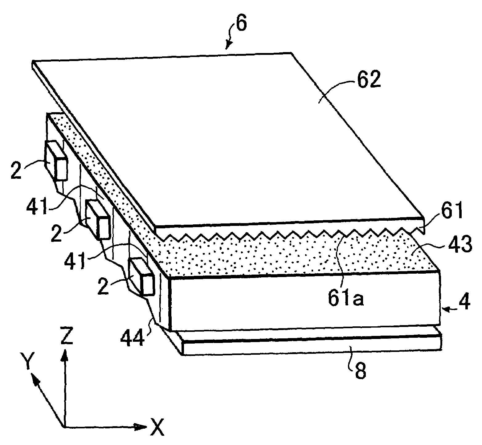
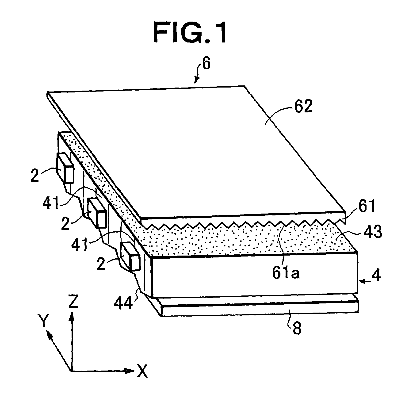
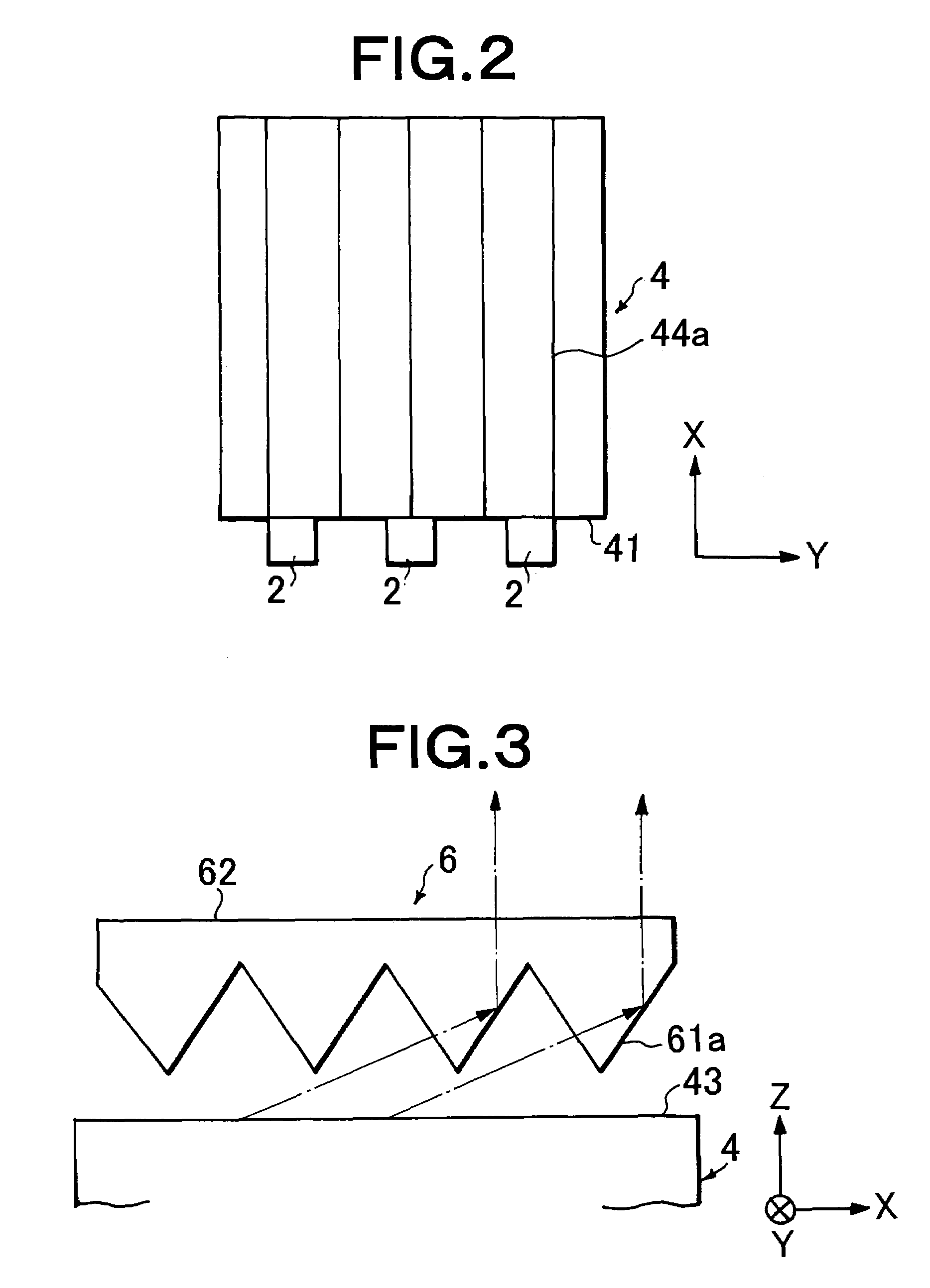
[0164]The surface of a stainless steel plate worked into a mirror surface and having an effective area of 34 mm×48 mm, and a thickness of 3 mm was partially roughened by a blasting process performed with respect to a region excluding a region of 3.5 mm from a side having a length of 34 mm, using glass beads having a particle diameter of 53 μm or less (FGB-400 manufactured by Fuji Seisakusho Co., Ltd.), and setting a distance from the stainless steel plate to a blowing nozzle was 32 cm and a blowing pressure was 5 kgf / cm2. Accordingly, a first mold having a shape transfer surface which was partially a rough surface was obtained.

[0165]On the other hand, a symmetrical lens pattern in which elongated lenses having a pitch of 50 μm were arranged in parallel to a side having a length of 48 mm was formed on the surface of a brass plate worked into a mirror surface and having an effective area of 34 mm×48 mm and a thickness of 3 mm by cutting. Accordingly, a second mold having the shape tra...

example 2

[0193]This example was performed in the same manner as in Example 1 except that a blasting process of a first mold was performed with respect to a region excluding a region of 3.0 mm from a side having a length of 34 mm, a blowing pressure in this case was changed in a range of 4 kgf / cm2 to 6 kgf / cm2, a blasting process of a second mold was performed with respect to the region excluding the region of 3.0 mm from the side having a length of 34 mm, and a blowing pressure in this case was set to 1.5 kgf / cm2.

[0194]An average inclination angle of a light outputting surface of an obtained light guide was 0° in a region of 3.0 mm from a light incident end surface, and 2.5° to 3.5° in the other region, and a middle portion of an effective light emitting region had a maximum value.

[0195]The cross-sectional shape of the elongated lens forming surface of the obtained light guide was as follows.

[0196](Region A: region of 3.0 mm from light incident end surface)

[0197]Outward convex curved line

[01...


PUM


Abstract

A light guide which guides light emitted from an LED includes a light incident end surface for receiving light, a light outputting surface for outputting a guided light, and a lens forming surface that has a plurality of elongated lenses arranged in parallel to each other and formed along the directivity of light incident from the LED, such that a plurality of micro regions are defined over the plurality of elongated lens. In the vicinity of the LED, a distribution of micro regions having an inclination angle between 20° and 50° is at least 10% over all micro regions. A light deflection element disposed adjacent to the light guide light outputting surface includes a light entrance surface having a plurality of lenses formed thereon that are parallel to each other and extend in a direction parallel to the light guide light incident end surface.

Description

TECHNICAL FIELD[0001]The present invention relates to a surface light source device of an edge light system, particularly to a surface light source device in which miniaturization and power consumption reduction are intended. The surface light source device is preferably applied, for example, to a backlight of a comparatively small liquid crystal display device for use as a display panel of a portable electronic device such as a cellular phone, and an indicator for various types of apparatuses.BACKGROUND ART [0002]In recent years, liquid crystal display devices have been broadly used as monitors of notebook-size portable computers and the like, or display sections of liquid crystal television sets or video integrated liquid crystal television sets, and further in other various fields. Each liquid crystal display device basically comprises: a backlight section; and a liquid crystal display element section. For the backlight section, an edge light system has been frequently used from ...

Claims


Application Information

Patent Timeline
Patent Type & Authority Patents(United States)
IPC IPC(8): F21V8/00
CPCG02B6/0016G02B6/0068G02B6/0038G02F1/1335
Inventor HAYASHI, YASUKOYAMASHITA, TOMOYOSHI
Owner MITSUBISHI CHEM CORP
Why Eureka
Try Eureka