Walk behind polisher

a technology of walking behind and polisher, which is applied in the direction of grinding heads, carpet cleaners, manufacturing tools, etc., can solve the problems of limiting the exposure of internal gears to dust from the working surface, and achieve the effects of reducing dust accumulation, reducing exposure of internal gears, and increasing directional stability

Inactive Publication Date: 2007-06-05
CAREX POWER TECH
View PDF7 Cites 20 Cited by
  • Summary
  • Abstract
  • Description
  • Claims
  • Application Information

AI Technical Summary

Benefits of technology

[0009]An improved walk behind polisher and grinder with increased directional stability and reduced dust accumulation to the essential internal components of the machine is disclosed. The improved walk behind polisher and grinder includes a drive motor carried by a frame. The drive motor rotates a central shaft, and the central shaft is fixed to a belt pulley. A rotary housing is rotatably mounted to the central shaft, and the belt pulley is disposed within the rotary housing. The rotary housing is adapted to receive at least one pinion shaft. Each pinion shaft is rotatably mounted to the rotary housing. An internal gear is fixed to the frame in mechanical engagement with each pinion shaft such that rotation of the central shaft causes the pinion shaft to rotate about its own axis in a given direction and to revolve around the central shaft in the opposite direction. A polishing plate or other surface work tool is fixed to each pinion shaft such that rotation of the pinion shaft causes rotation of each polishing plate. The polishing plates contact and apply frictional force to a working surface to effect polishing of the working surface. Suitable surface work tools include any item that is attached to a mounting plate that fulfills the functions including scrubbing, buffing, grinding, or polishing of floor surfaces or similar, essentially continuous, surfaces.
[0010]In order to minimize exposure of the internal gear to dust from the working surface, a baffled wall is provided. The baffled wall includes a bushing defined by a substantially cylindrical wall substantially surrounding the internal gear, and a brush ring substantially surrounding the bushing. In one embodiment, the bushing is fixed to the rotary housing, and the brush ring is attached to the frame. In another embodiment, the brush ring is fixed to the rotary housing, and the bushing is attached to the frame. The brush ring is equipped with a plurality of bristles which contact the bushing. As the upper surface of the rotary housing rotates proximate the frame, the bushing rotates proximate the brush ring. This causes the bristles to effectuate brushing of the bushing, limiting the exposure of the internal gear to dust from the working surface.

Problems solved by technology

This causes the bristles to effectuate brushing of the bushing, limiting the exposure of the internal gear to dust from the working surface.

Method used


Image

  • Walk behind polisher
  • Walk behind polisher
  • Walk behind polisher

Examples


Embodiment Construction

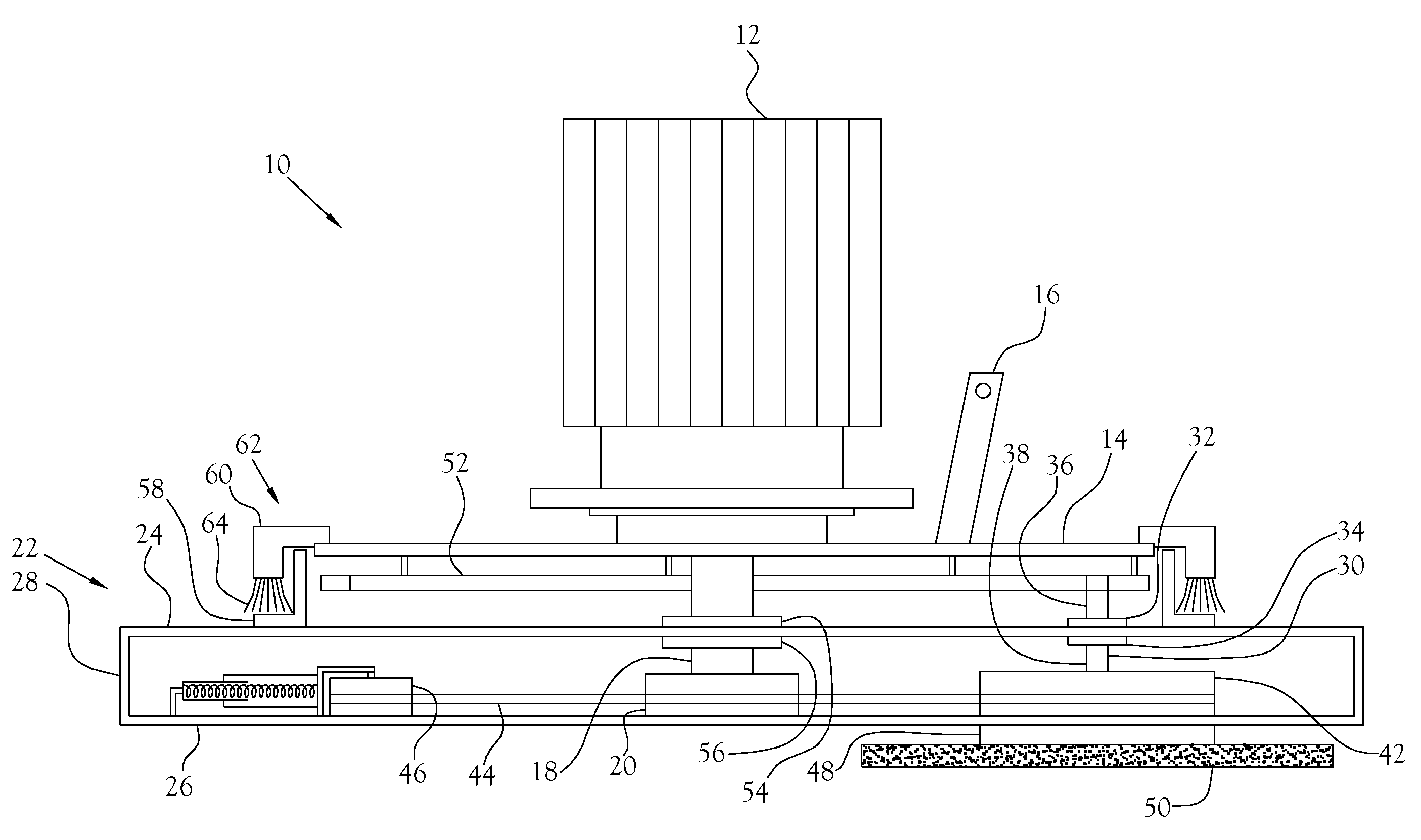
[0016]An improved walk behind polisher and grinder is disclosed. The improved walk behind polisher and grinder, illustrated at 10 in the figures, provides a surface polishing machine capable of operation with increased directional stability and reduced dust accumulation to the essential internal components of the machine.

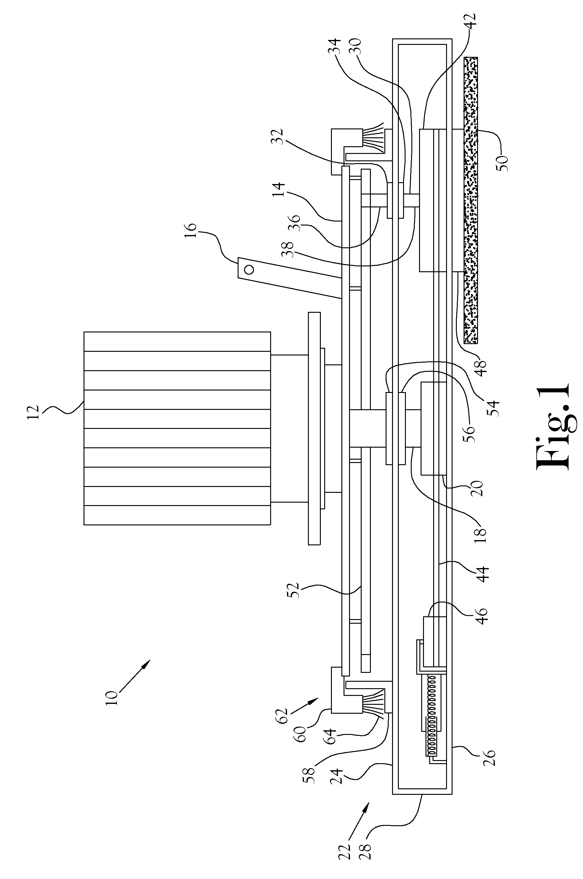
[0017]FIG. 1 is a cross-sectional view in schematic form of an improved walk behind polisher and grinder 10 constructed in accordance with several features of the present invention. The simplified schematic does not illustrate various connections, for example, power and ground connections to the various components; however, those skilled in the art will recognize the need for such wiring and understand how to wire such a circuit, based on the components ultimately selected for use. The improved walk behind polisher and grinder 10 includes a drive motor 12 mounted on a frame 14. The frame 14 is provided with attachment members 16 for control devices not shown in the ...


PUM


Abstract

An improved walk behind polisher and grinder is disclosed. The improved walk behind polisher and grinder provides a surface polishing machine capable of operation with increased directional stability and reduced dust accumulation to the essential internal components of the machine. The improved walk behind polisher and grinder includes a drive motor mounted on a frame. The drive motor rotates a central shaft, and the central shaft supports a belt pulley and a rotary housing. The belt pulley mechanically communicates with at least one pinion shaft through an endless drive. Each pinion shaft is mechanically engaged by an internal gear such that rotation of the central shaft causes the pinion shaft to rotate about their own axes in a given direction and to revolve around the central shaft in the opposite direction.

Description

CROSS-REFERENCE TO RELATED APPLICATIONS[0001]Not ApplicableSTATEMENT REGARDING FEDERALLY SPONSORED RESEARCH OR DEVELOPMENT[0002]Not ApplicableBACKGROUND OF THE INVENTION[0003]1. Field of Invention[0004]This invention pertains to surface polishing machines. More particularly, this invention pertains to an improved surface polishing and grinding machine for conducting various surface polishing operations such as scrubbing, buffing, grinding, or polishing of floor surfaces or similar, essentially continuous surfaces.[0005]2. Description of the Related Art[0006]It is often necessary to sand, polish, or otherwise refinish flooring surfaces such as concrete, stone, or other such flooring surfaces. The conventional tool used in performing this type of surface polishing is a hand operated polishing machine. This type of machine typically utilizes surface processing apparatus including at least one frictional surface rotated by an electric motor, a combustion engine, or similar power means. ...

Claims


Application Information

Patent Timeline
Patent Type & Authority Patents(United States)
IPC IPC(8): B24B23/00
CPCA47L11/16A47L11/4069B24B7/186B24B41/047
Inventor PADGETT, STEPHEN DAVIDLIVELY, THOMAS ROY
Owner CAREX POWER TECH
Why Eureka
Try Eureka