
Thermoformable acoustic sheet

Inactive Publication Date: 2007-06-05
ZEPHYROS INC
View PDF48 Cites 35 Cited by
  • Summary
  • Abstract
  • Description
  • Claims
  • Application Information

AI Technical Summary

Benefits of technology

[0007]In one form of the invention, the thermoplastic fibres are treated with an adhesive coating to increase the airflow resistance.
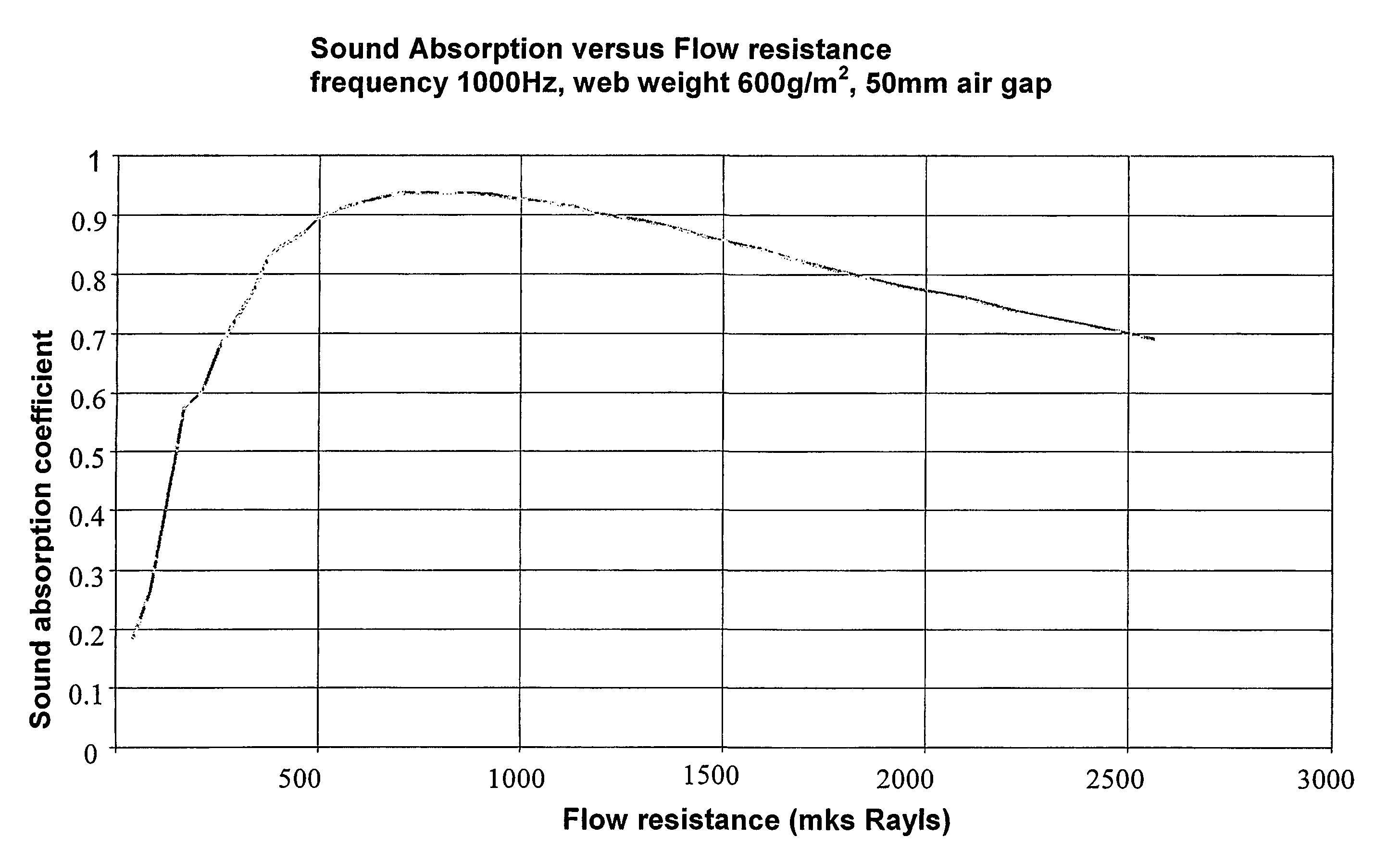
[0032]For hood insulator applications, the appearance must be consistent and low gloss. Appearance can be influenced by the fibre properties and binder fibres tend to develop gloss during compaction and subsequent molding. To minimise gloss, the option of using an additional layer of fibrous material as the coating with each layer having significantly different fibre blend ratios is preferred. A face web should have a relatively low proportion of binder fibre, preferably 10–20% and a back web should have a very high binder ration, from 60–100%, preferably 80%. The back web will significantly contribute to flow resistance to assure excellent sound absorption, whilst the facing web assists in resisting marring during the process.

Problems solved by technology

The difficulties associated with this product include the fact that the moulding process is relatively slow taking up to 2½ minutes per moulded part.
Additionally, the use of resinated fibreglass is undesirable because of its inherent undesirable handling problems while the resins can release toxic gases during the moulding process.
Attempts to produce a suitable thermoformable material from thermoplastic textile for underbonnet insulator have been unsuccessful due to one or more of the failure of the materials to meet requirements of low sag modulus typically encountered at operating temperatures, unsuitable moulding performance, and lack of uniformity of air flow resistance required for acoustic absorption performance.

Method used


Image

  • Thermoformable acoustic sheet
  • Thermoformable acoustic sheet
  • Thermoformable acoustic sheet

Examples


example 1

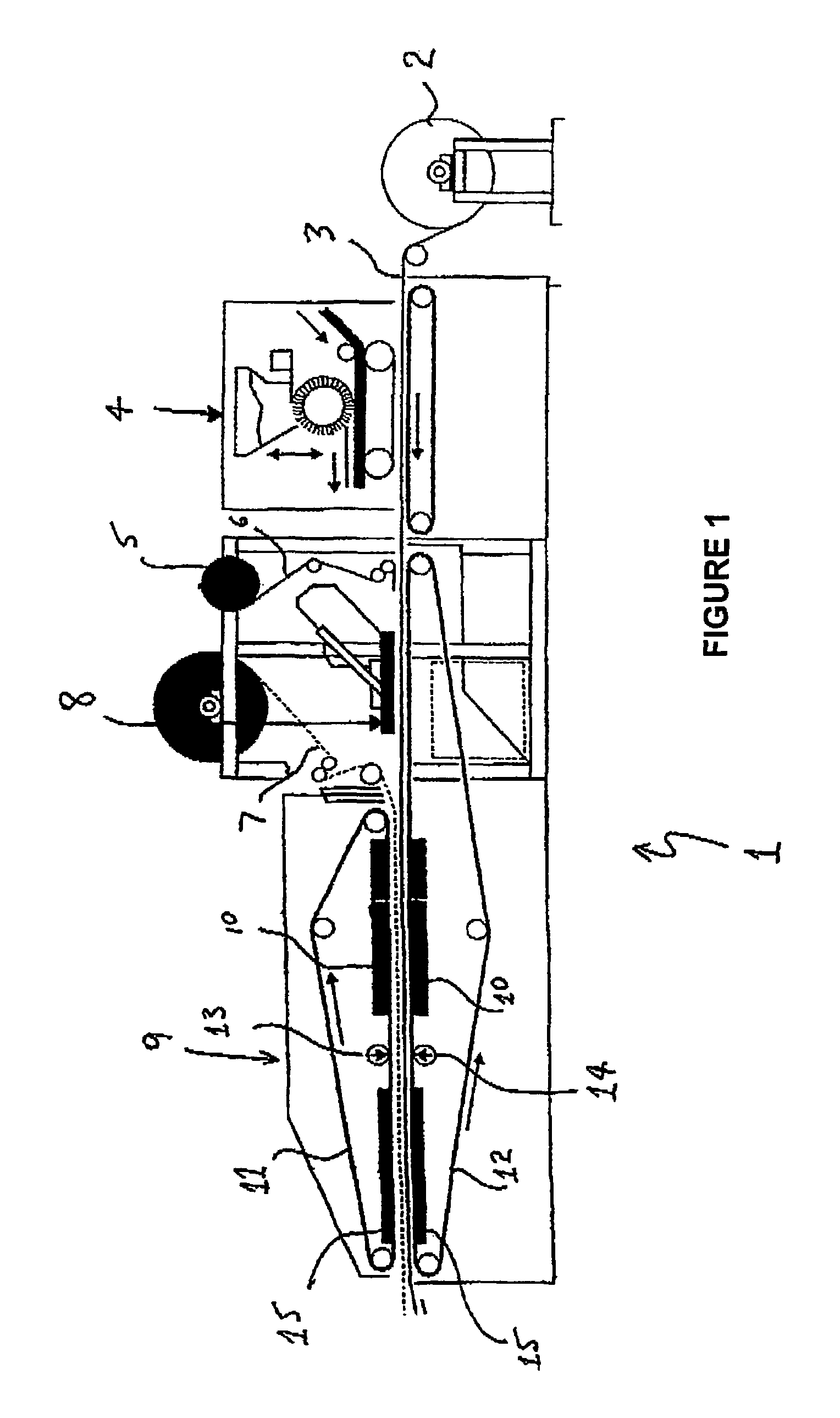
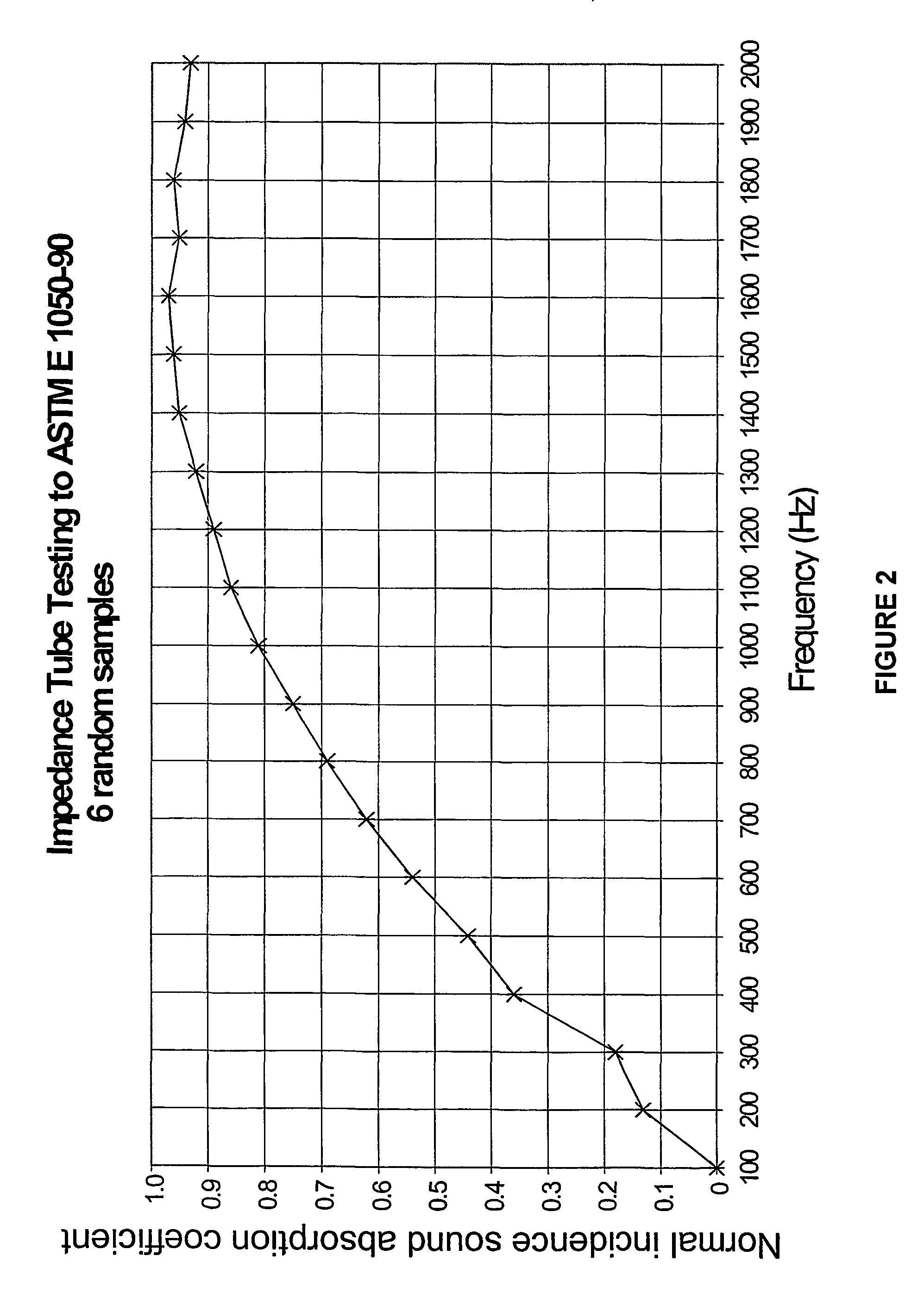
[0047]A sample was prepared using the above described machine and tested using an impedance tube with a 50 mm air gap to ASTME E 1050-90. The properties of the sample were:[0048]carrier formulation 30% polypropylene (adhesive fibre) and 70% polyester (high melt);[0049]web material was a needle punched mixture in roll form;[0050]carrier web weight 450 g / m2; and[0051]polyester non-woven fabric facing web weight 50 g / m2 adhered with a small (15–20 g) of polypropylene powder.

[0052]The average air flow resistance of the sample was 300–400 mks Rayls.

[0053]FIG. 2 is a plot of average incident sound absorption versus frequency for six randomly selected samples prepared according to this example.

example 2

[0054]A sample was prepared and tested in the same manner as in Example 1 with the following specifications:[0055]50% high melt fibre of 6 denier;[0056]50% adhesive fibre of 4 denier; and[0057]web weight 700 g / m2.

[0058]The air flow resistance of the sample was in the range of 300–400 mks Rayls.

example 3

[0059]A sample was prepared and tested in the same manner as in Example 1 with the following specifications:[0060]30% high melt polyester fibre of 6 denier;[0061]70% adhesive polyester fibre of 4 denier;[0062]web weight 600 g / m2.

[0063]The air flow resistance of the sample was in the range of 700–850 mks Rayls.


PUM

PropertyMeasurementUnit
Temperatureaaaaaaaaaa
Fractionaaaaaaaaaa

Abstract

A thermoformable acoustic sheet formed by a compressed fibrous web including high melt and adhesive thermoplastic fibres in which the adhesive fibres are at least partially melted so that in the compressed web the adhesive fibres at least partially coat the high melt fibres and reduce the interstitial space in the fibre matrix. Also included is a method of producing a thermoformable acoustic sheet which includes the steps of heating a fibre web including high melt and adhesive thermoplastic fibres to at least partially melt the adhesive fibres and compressing the web to form a sheet so that the adhesive fibres at least partially coat the high melt fibres to reduce the interstitial space in the fibre matrix.

Description

BACKGROUND OF THE INVENTION[0001]This invention relates to materials for acoustic absorption. More particularly it relates to thermoformable acoustic sheets.[0002]Sounds absorption is required in a wide variety of industrial and domestic applications. In many of these applications it is desirable that the acoustic material conforms to the shape of a surface for example or otherwise retains a particular shape. In such applications it is desirable that the acoustic sheet can be heat moulded to the required shape to provide relative ease and speed of production. Sound absorption can be a function of depth of air space, air flow resistance, mass, stiffness and the acoustic impedance of any porous media behind the acoustic sheet. Therefore, adding a third dimension for example by moulding to a required shape increases stiffness and can add practical and aesthetic value. Importantly a three dimensionally shaped material provides its own air space. The shape therefore has a major influence...

Claims


Application Information

Patent Timeline
IPC IPC(8): A01K1/015E04B1/82B32B3/10B29C43/22D04H1/542B29C43/28B29C51/00B32B5/26B60R13/08D04H1/42D04H1/46D04H1/54D04H1/541D04H1/55D04H1/559D04H1/58D04H1/593D04H1/60D04H3/16D04H13/00E04B1/74E04B1/84G10K11/00G10K11/16G10K11/162
CPCD04H1/46D04H1/541D04H1/55D04H1/559D04H1/58D04H1/593D04H1/60D04H3/16G10K11/162B29C43/228B29C43/28B29C51/004D04H1/42D04H1/54Y10T428/24B29K2067/00B29K2067/046B29K2105/06B60R13/08Y10T428/24636Y10T428/24322D04H1/4291D04H1/435Y10T428/249953Y10T428/249921Y10T428/249924D04H1/5418E04B1/84
Inventor COATES, MICHAEL WILLIAMKIERZKOWSKI, MAREK
Owner ZEPHYROS INC
Learn More