Electricity storage device

a technology of electric storage and storage device, which is applied in the direction of non-aqueous electrolyte cells, cell components, electrochemical generators, etc., can solve the problems of battery performance deterioration, battery has not been used in a device, and battery requires a longer charging time, etc., to achieve the effect of higher energy density

Inactive Publication Date: 2007-06-05
NEC CORP
View PDF10 Cites 13 Cited by
  • Summary
  • Abstract
  • Description
  • Claims
  • Application Information

AI Technical Summary

Problems solved by technology

However, since the lithium-ion secondary battery has a small reaction rate in an electrode reaction, a large current leads to significant deterioration in battery performance.
Therefore, when used in a small electronic device, the battery requires a longer charging time.
Also, the battery has not been used in a device such as an electric automobile requiring a large current.
However, since it has a small energy density and thus size reduction has been difficult, it has not been utilized in mobile electronic devices.
Furthermore, it has not been extensively mounted in an electric automobile due to its poor capacity.
However, since its voltage and energy density are low, it has not been applied to an electric automobile in which a motor is driven by electric power.
As described above, a lithium-ion secondary battery cannot be used for a large current and an electric double layer capacitor or lead storage battery cannot give an adequate energy density required for a small electronic device.
In other words, although there have been a variety of proposals for a charge storage device which can be applied to a mobile electronic device or electric automobile, no charge storage devices with a higher energy density through which a large current can be drawn have been obtained.

Method used


Image

  • Electricity storage device
  • Electricity storage device
  • Electricity storage device

Examples


example 1

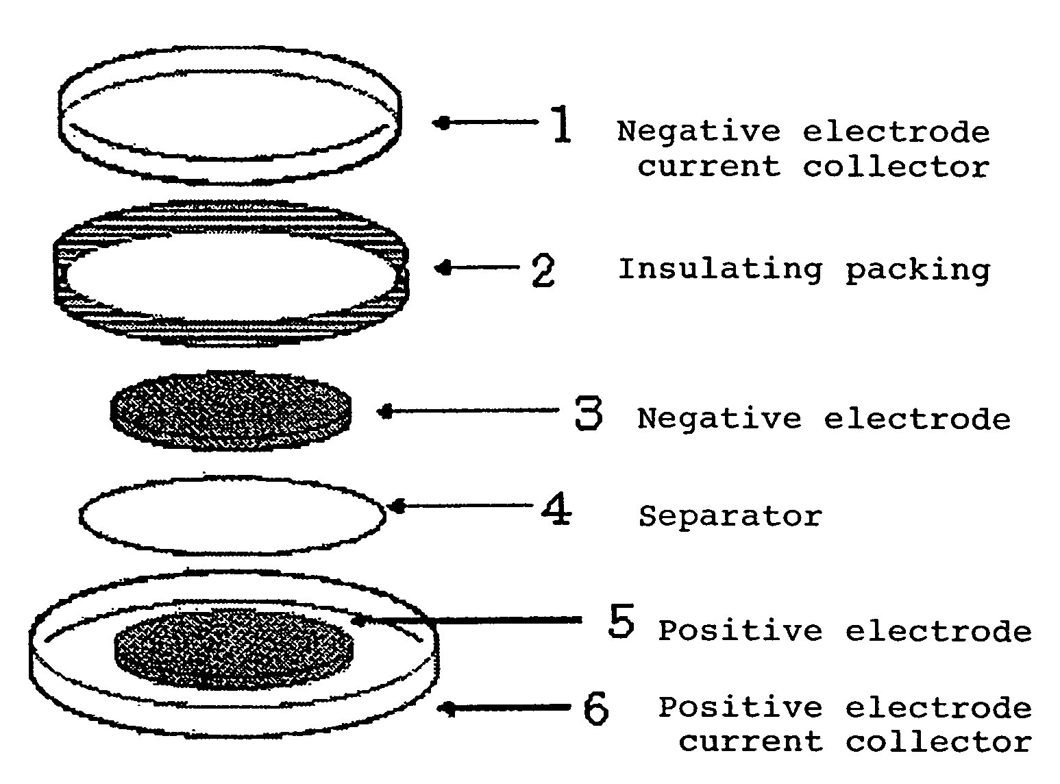
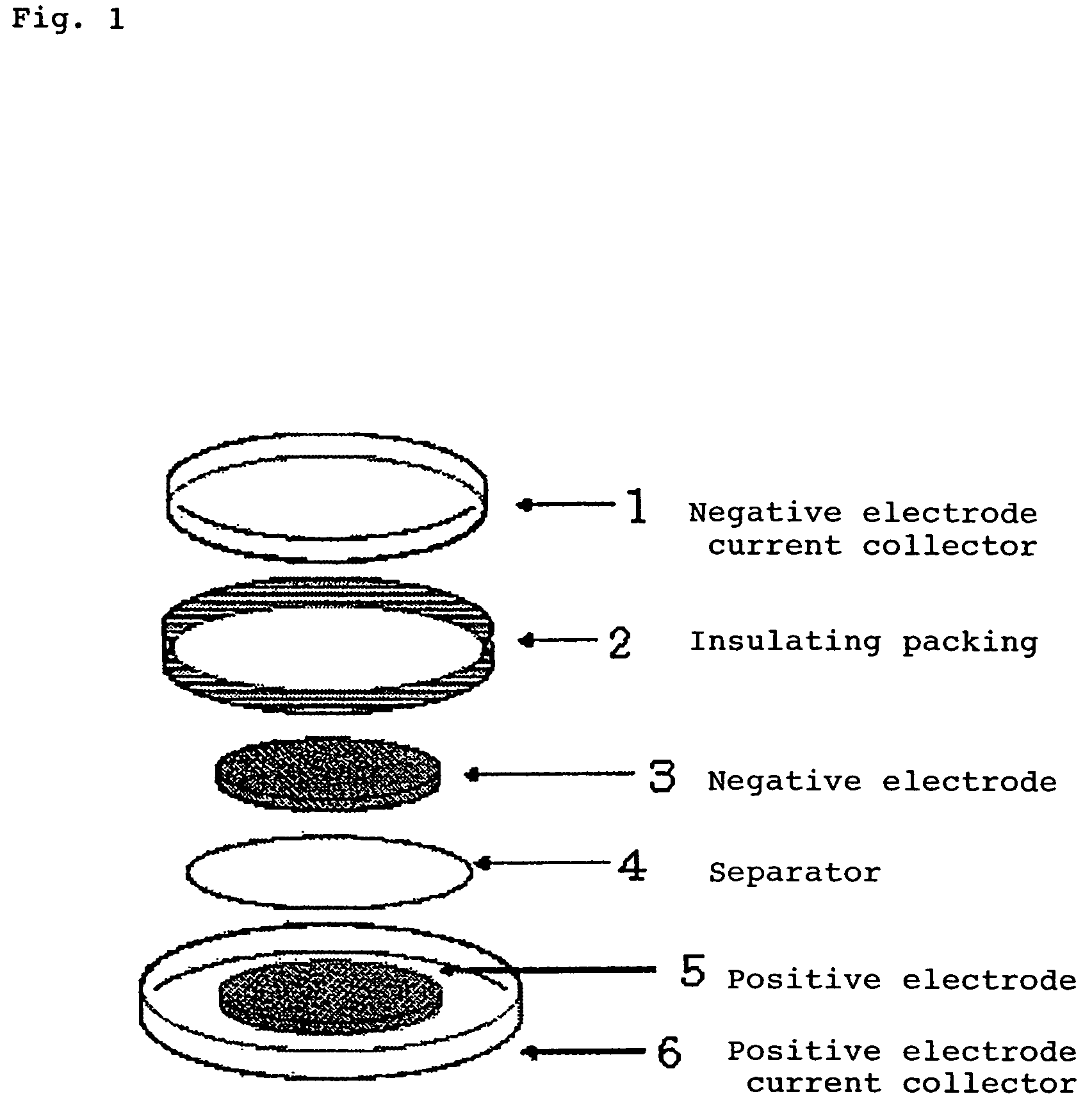
[0099]Twenty five milligrams of the polymethacrylate represented by formula (7) prepared above, 200 mg of graphite powder and 25 mg of a polytetrafluoroethylene resin binder were weighed and blended in an agate mortar. After dry mixing for 10 min, the resulting mixture was roller extended while applying pressure to give a thin electrode plate with a thickness of 215 μm. The thin electrode plate was dried overnight in vacuo at 80° C., punched into disks with a diameter of 12 mm and shaped into an electrode for a charge storage device. The total weight of the electrode was 14.4 mg, which contains 1.44 mg (10 wt %) of the polymethacrylate represented by formula (7). A bulk density of the electrode was 0.533 g / cm3.

[0100]The electrode was immersed in an electrolyte solution to allow the electrolyte solution to enter vacancies. An electrolyte solution used was a mixed solution of ethylene carbonate and diethyl carbonate (mixing ratio=3:7) containing 1 mol / L of LiPF6 as electrolyte salt. T...

example 2

[0108]Twenty five milligrams of the polymethacrylate represented by formula (8) prepared above, 200 mg of graphite powder and 25 mg of a polytetrafluoroethylene resin binder were weighed and blended in an agate mortar. The subsequent procedure was conducted as described in Example 1, to prepare an electrode. Then, a charge storage device was assembled using an electrolyte, a separator, a positive electrode current collector and a negative electrode current collector as described in Example 1.

[0109]The charge storage device thus prepared had an equilibrium potential of 2.7 V. The charge storage device obtained was charged at a fixed current of 1 mA and charging was terminated when a voltage reached 4.0 V. The charge storage device after charging was disassembled. By analyzing the positive electrode, it was observed that a radical concentration was reduced and a corresponding 2,2,5,5-tetramethylpyrrolidinoxyl cation was formed. The cation was stabilized by an electrolyte anion PF6−.

[0...

example 3

[0112]Twenty five milligrams of the polymethacrylate represented by formula (9) prepared above, 200 mg of graphite powder and 25 mg of a polytetrafluoroethylene resin binder were weighed and blended in an agate mortar. The subsequent procedure was conducted as described in Example 1, to prepare an electrode. Then, a charge storage device was assembled using an electrolyte, a separator, a positive electrode collector and a negative electrode collector as described in Example 1.

[0113]The charge storage device thus prepared had an equilibrium potential of 2.7 V. The charge storage device obtained was charged at a fixed current of 1 mA and charging was terminated when a voltage reached 4.0 V. The charge storage device after charging was disassembled. By analyzing the positive electrode, it was observed that a radical concentration was reduced and a corresponding 2,2,5,5-tetramethylpyrrolinoxyl cation was formed. The cation was stabilized by an electrolyte anion PF6−.

[0114]In the manner ...


PUM

PropertyMeasurementUnit
thicknessaaaaaaaaaa
diameteraaaaaaaaaa
weightaaaaaaaaaa

Abstract

A charge storage device such as a battery, wherein a positive electrode comprises a nitroxyl compound having a structure of a nitroxyl cation moiety represented by formula (I) in an oxidized state while having a structure of a nitroxyl radical moiety represented by formula (II) in a reduced state and a reaction represented by reaction formula (A) in which an electron is transferred between these states is used as a positive electrode reaction. The charge storage device can have a higher energy density and can be used at a large current.

Description

TECHNICAL FIELD[0001]This invention relates to a charge storage device with a large energy density from which a large current can be drawn at one time.BACKGROUND ART[0002]As laptop personal computers, mobile phones and electric automobiles have rapidly expanded their markets, there have been needed a charge storage device with a higher energy density and a large current. Among others, a lithium ion secondary battery wherein a positive electrode uses a lithium-containing transition metal oxide while a negative electrode uses a carbon material has been used as a high-energy secondary battery in a variety of electronic devices.[0003]However, since the lithium-ion secondary battery has a small reaction rate in an electrode reaction, a large current leads to significant deterioration in battery performance. Therefore, when used in a small electronic device, the battery requires a longer charging time. Also, the battery has not been used in a device such as an electric automobile requirin...

Claims


Application Information

Patent Timeline
Patent Type & Authority Patents(United States)
IPC IPC(8): H01M4/60C08F20/36C08F8/06C08F20/26H01G9/00H01G9/035H01G9/04H01G9/042H01G11/08H01M6/16H01M10/05H01M10/0564
CPCH01M4/137H01M4/60H01M4/608H01M10/052H01M2004/028Y02E60/122Y02E60/10
Inventor NAKAHARA, KENTAROIWASA, SHIGEYUKISATOH, MASAHARUIRIYAMA, JIROMORIOKA, YUKIKO
Owner NEC CORP
Why Eureka
Try Eureka