Resistorless bias current generation circuit

a bias current and resistance-less technology, applied in pulse generators, pulse techniques, instruments, etc., can solve the problems of bias current in the conventional approach being likewise susceptible to process and temperature variations, and achieve the effect of reducing the susceptibility to process and temperature variation, power and power variation

Active Publication Date: 2007-06-05
SAMSUNG ELECTRONICS CO LTD
View PDF6 Cites 28 Cited by
  • Summary
  • Abstract
  • Description
  • Claims
  • Application Information

AI Technical Summary

Benefits of technology

[0007]In particular, in one embodiment, the bias current generator of the present invention generates a bias current using a PTAT current generator and an IPTAT current generator comprising exclusively active circuit elements, for example transistors. No passive elements, such as resistors, are employed. The generated bias current is substantially a function of the respective aspect ratios of transistors of current paths of the device. In this manner, the resulting generated bias current has greatly reduced susceptibility to variation in applied power, process and temperature.

Problems solved by technology

Since resistors are highly susceptible to process variation and operating temperature variation, the resulting bias current in the conventional approach is likewise susceptible to process and temperature variations.

Method used


Image

  • Resistorless bias current generation circuit
  • Resistorless bias current generation circuit
  • Resistorless bias current generation circuit

Examples


first embodiment

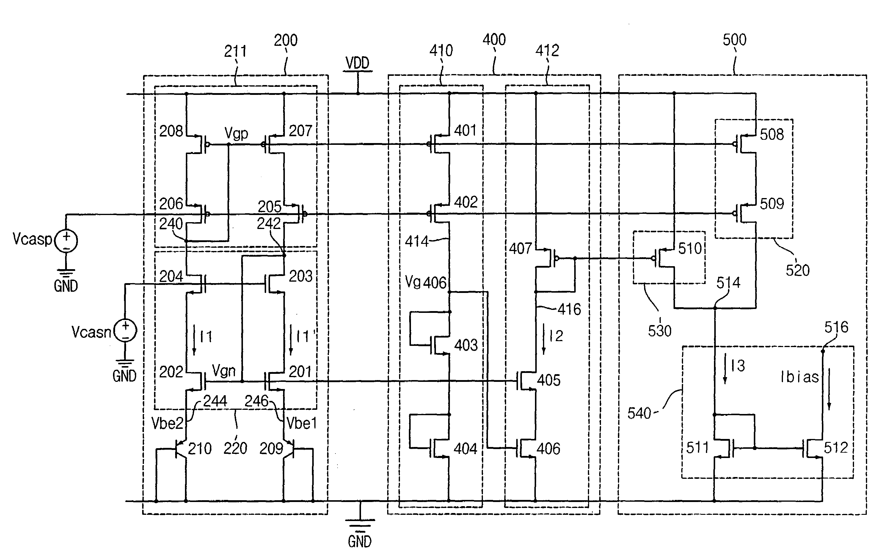
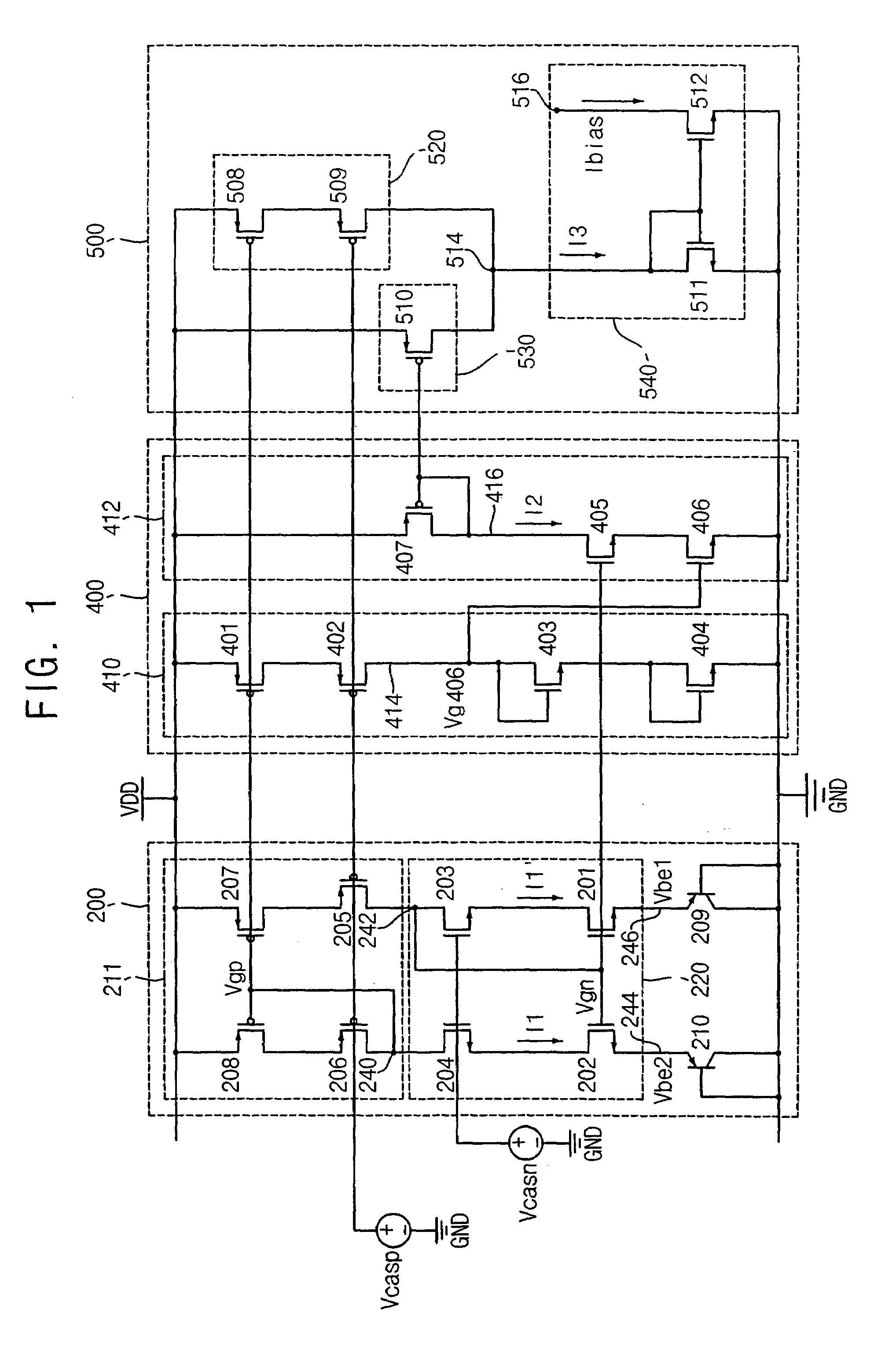
[0052]FIG. 1 is a circuit diagram of a bias current generating circuit in accordance with the present invention. With reference to FIG. 1, the bias generating circuit includes a proportional-to-absolute-temperature (PTAT) current generator 200, an inverse-proportional-to-absolute-temperature (IPTAT) current generator 400, and a summing circuit 500.

[0053]In one embodiment, the PTAT current generator 200 and the IPTAT current generator 400 employ exclusively active elements, such as NMOS and PMOS transistors and bipolar junction transistors, and therefore do not include passive elements, such as resistors. The PTAT current generator 200 generates a first sub-current I1 that is proportional to temperature. The IPTAT current generator 400 generates a second sub-current I2 that is inverse-proportional to temperature. The summing circuit 500 sums the first sub-current I1 and the second sub-current I2 to generate a sum current I3 that is used to generate a bias current Ibias. Since the PTA...

second embodiment

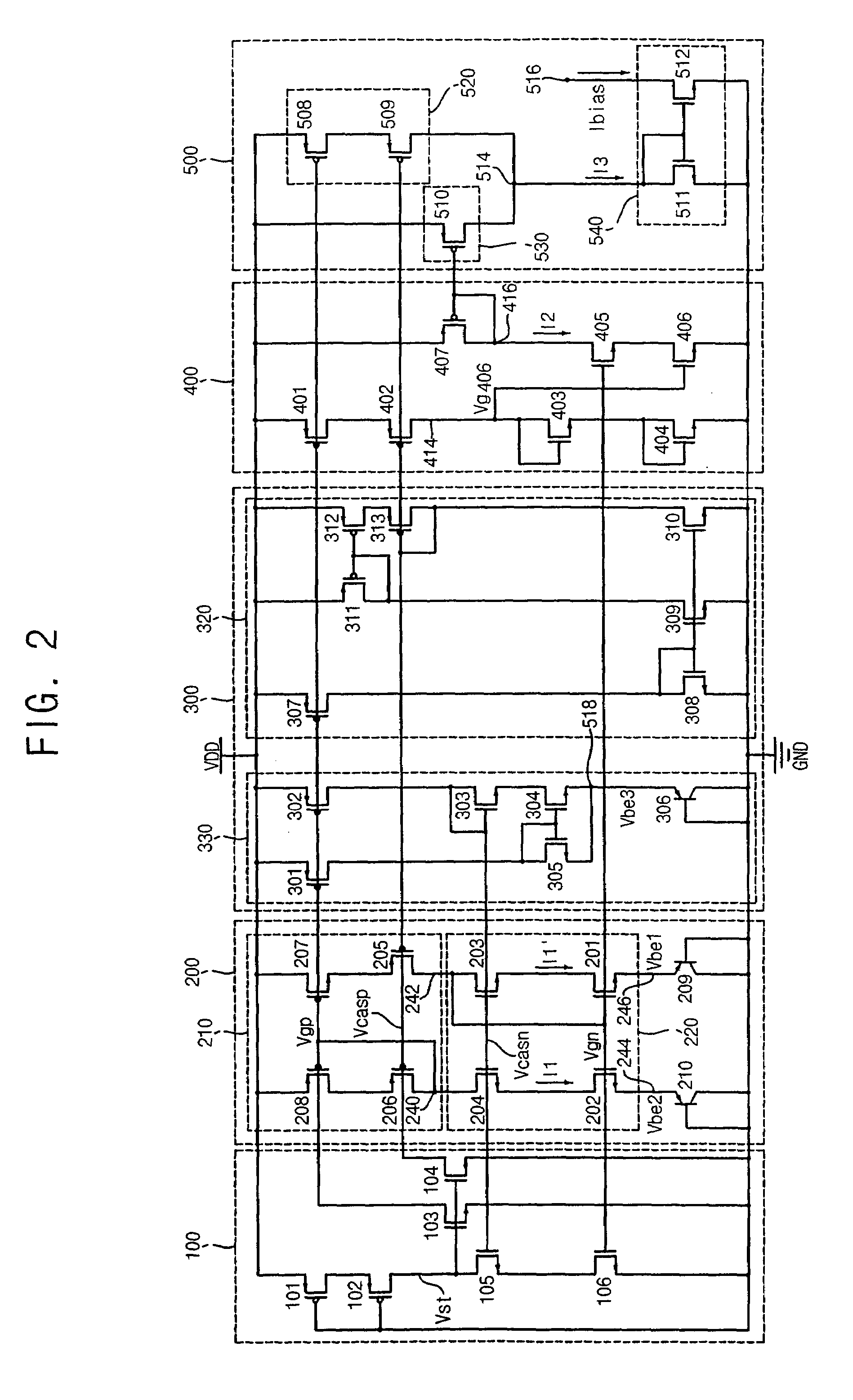
[0101]FIG. 2 is a circuit diagram of a bias current generating circuit in accordance with the present invention. With reference to FIG. 2, the bias generating circuit includes a proportional-to-absolute-temperature (PTAT) current generator 200, an inverse-proportional-to-absolute-temperature (IPTAT) current generator 400, and a summing circuit 500, as described above, and further includes a bias voltage generator 300 and a start-up circuit 100.

[0102]The bias voltage generator 300 includes a first voltage generator 320 and a second voltage generator 330. The first bias voltage generator 320 generates the first bias voltage Vcasp that is provided to the PMOS cascode current mirror 210 of the PTAT current generator 200. The second bias voltage generator 330 generates the second bias voltage Vcasn that is provided to the NMOS cascode current mirror 220 of the PTAT current generator 200.

[0103]The first bias voltage generator 320 includes an eleventh PMOS transistor 307 and an eleventh NM...


PUM


Abstract

A bias current generating circuit generates a reliable and consistent bias current, irrespective of variation in applied power, process and temperature. In one embodiment, the bias current generator generates a bias current using a PTAT current generator and an IPTAT current generator comprising exclusively active circuit elements, for example transistors. No passive elements, such as resistors, are employed. The generated bias current is substantially a function of the respective aspect ratios of transistors of current paths of the device. In this manner, the resulting generated bias current has greatly reduced susceptibility to variation in applied power, process and temperature.

Description

RELATED APPLICATIONS[0001]This application claims priority under 35 U.S.C. 119 to Korean Patent Application No. 10-2004-0093100, filed on Nov. 15, 2004, the content of which is incorporated herein by reference in its entirety.FIELD OF THE INVENTION[0002]The present invention relates generally to an integrated circuit device, and more particularly, to a bias current generating circuit for an integrated circuit device.BACKGROUND OF THE INVENTION[0003]Bias current generating circuits are commonly employed in integrated circuit devices in order to generate a bias current from an external power supply voltage. An ideal bias current generating circuit generates a consistent bias current that is independent of variation in applied power, process parameters and temperature.[0004]A conventional bias current generation circuit is disclosed in U.S. Pat. No. 6,201,436, the content of which is incorporated herein by reference. Such a circuit employs a first current generator in which a first gen...

Claims


Application Information

Patent Timeline
Patent Type & Authority Patents(United States)
IPC IPC(8): G05F1/10
CPCG05F3/245G05F3/247G05F3/26
Inventor ZHANG, WEICHENGLEE, SEUNGHOON
Owner SAMSUNG ELECTRONICS CO LTD
Why Eureka
Try Eureka