
Open layered steel cord with high breaking load

a technology of open layered steel and high breaking load, which is applied in the field of steel cord, can solve the problems of high breaking load, high cost and weight of tires, and more difficult to achieve a fully open structure, and achieve the effect of reducing the tensile strength of preformed steel filaments, and controlling the decreas

Inactive Publication Date: 2007-06-12
NV BEKAERT SA
View PDF12 Cites 17 Cited by
  • Summary
  • Abstract
  • Description
  • Claims
  • Application Information

AI Technical Summary

Benefits of technology

[0013]It is another object of the present invention to provide a steel cord with a high breaking load, a high resistance against fatigue and a high resistance against corrosion.
[0014]It is further object of the present invention to provide a steel cord with a high breaking load, a small steel cord diameter and a good rubber penetration.
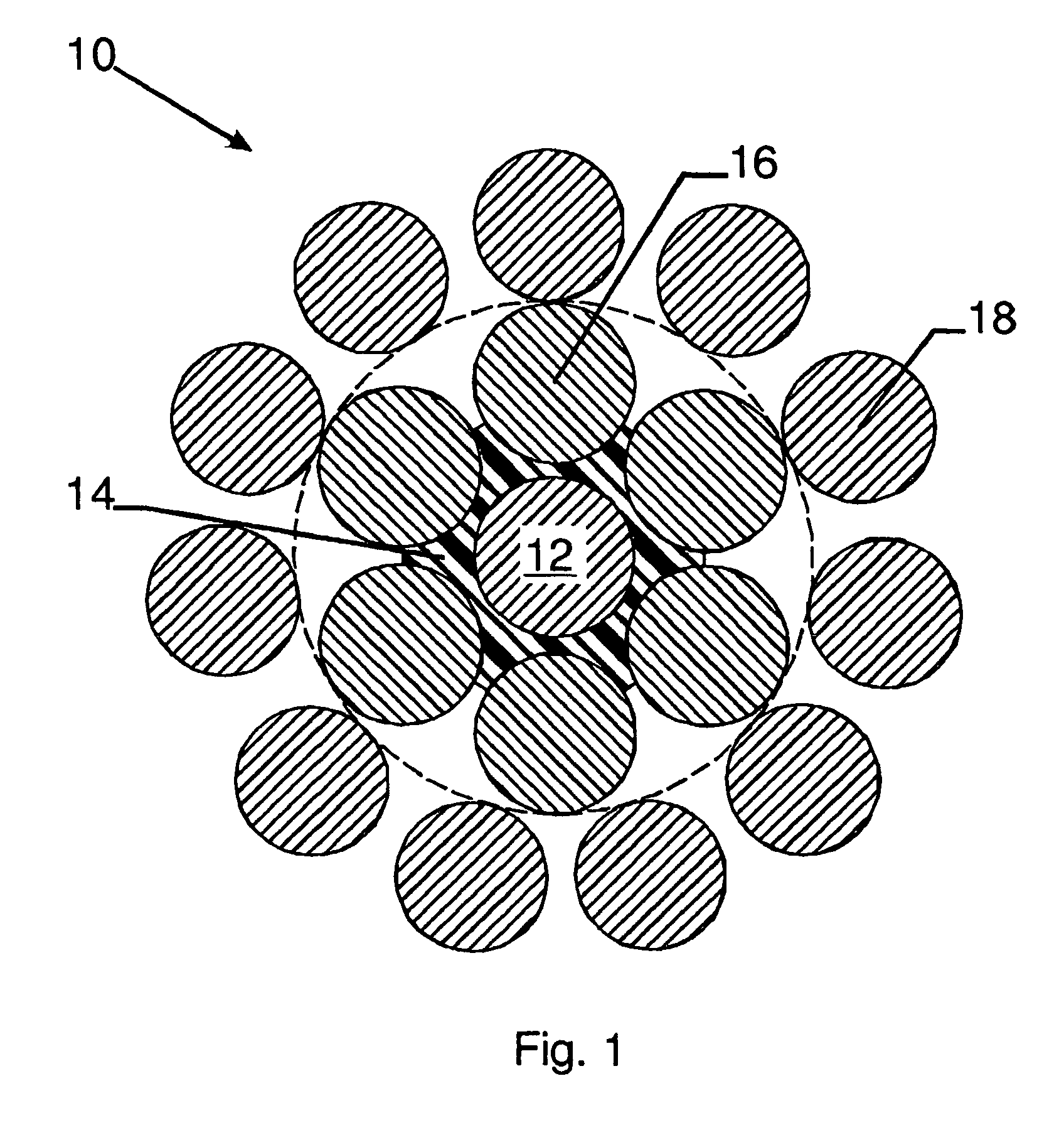
[0021]The polymer around the core steel filament fills the holes between the core steel filament and the intermediate steel filaments and avoids heavy fretting between the intermediate steel filaments and the core steel filament.
[0023]Preferably the preforming of the outer steel filaments is a polygonal preforming such as disclosed in EP-B-0 734 468. A polygonal preforming of the outer steel filaments has the advantage that full rubber penetration until the intermediate steel filaments is obtained by means of a small degree of preforming. This small degree of preforming has two advantages.
[0025]A second advantage is that It does not decrease substantially the tensile strength of the polygonally preformed steel filaments. It is hereby understood that plastic deforming other than further drawing usually decreases the tensile strength of the preformed steel filaments. With appropriate polygonal preforming, however, this decrease is controlled and limited.

Problems solved by technology

This open character of the steel cord, however, is directly opposite to the goal of obtaining a high breaking load (a) and a high fatigue resistance, since it reduces the compactness and the amount of steel cross-section per total cross-section, and because for a high breaking load and high fatigue resistance a lot of small filaments are required, thus making it more difficult to achieve a fully open structure.
A low cord diameter (d) is required to reduce the amount of rubber used to embed the steel cords in, and hence the total cost and weight of the tire.
However a low cord diameter is opposed to a high breaking load since less steel is available.

Method used


Image

  • Open layered steel cord with high breaking load
  • Open layered steel cord with high breaking load

Examples


Embodiment Construction

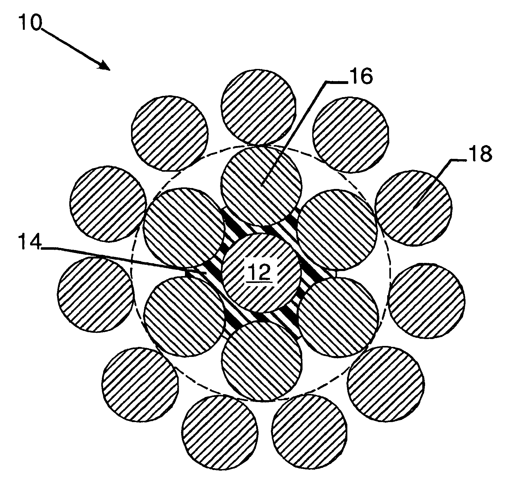
[0031]FIG. 1 shows the cross-section of a steel cord 10 according to the invention. The steel cord 10 comprises a steel core filament 12 of 0.30 mm. This steel core filament 12 has been coated in advance, e.g. by means of an extrusion process, by a polymer 14 such as polyethylene terephtalate (PET). PET has proven to be a suitable polymer because of its low absorption of humidity and of its high resistance against mechanical fretting of neighbouring filaments. Prior to the twisting process of the steel cord 10, the diameter of the PET coated steel core filament 12, 14 amounts to about 0.38 mm. An intermediate layer of six intermediate steel filaments 16 is twisted around the PET coated core steel filament 12, 14. The diameter of the intermediate steel filaments 16 is 0.30 mm. The twisting step of the intermediate steel filaments 16 is 9 mm in S-direction. Due to the radial pressure of the intermediate layer filaments 16, the PET 14 flows somewhat between the intermediate steel filam...


PUM

PropertyMeasurementUnit
tensile strengthaaaaaaaaaa
diameters dcaaaaaaaaaa
tensile strengthaaaaaaaaaa

Abstract

A steel cord adapted for the reinforcement of elastomers includes: a core steel filament with a diameter dc and coated with a polymer, six intermediate steel filaments with a diameter di smaller than or equal to dc, the intermediate steel filaments being twisted around the core steel filament, ten to eleven outer steel filaments with a diameter do, smaller than or equal to di wherein these outer steel filaments are twisted around the intermediate steel filaments, and the outer steel filaments are preformed in order to allow rubber penetration inside the cord. The core steel filament, the intermediate steel filaments, and the outer steel filaments all have a tensile strength of at least 2600 MPa. The cord has an outer diameter D according to the following formula: D≦dc+2×di+2×do+0.1 mm, wherein all diameters are expressed in millimeters (mm).

Description

FIELD OF THE INVENTION[0001]The present invention relates to a steel cord adapted for the reinforcement of elastomers.BACKGROUND OF THE INVENTION[0002]Steel cords are commonly used for the reinforcement of elastomers such as rubber tires.[0003]Particularly for dynamic applications such as rubber tires, a lot of requirements are Imposed on steel cords. Steel cords are required to have:[0004](a) a high breaking load;[0005](b) a high resistance against fatigue;[0006](c) a high resistance against corrosion.[0007](d) a low cord diameter[0008]A high breaking load (a) can be obtained by twisting the steel cord from high-tensile strength filaments, i.e. steel filaments with a high-carbon steel composition which have been subjected to a high final deformation through a drawing operation so that a high tensile strength is obtained. Supposing an equal starting steel wire diameter for the half-product, the finer the final filament diameters the higher the deformation ratio and the higher the ob...

Claims


Application Information

Patent Timeline
Patent Type & Authority Patents(United States)
IPC IPC(8): D02G3/48D07B1/06D07B1/16
CPCB60C9/0007D07B1/0646D07B1/0633Y10T152/1081D07B2201/2002D07B2201/2006D07B2201/2012D07B2201/2023D07B2201/2029D07B2201/203D07B2201/2031D07B2201/204D07B2201/2046D07B2201/2051D07B2201/2059D07B2201/2065D07B2205/2039D07B2205/3057D07B2401/208D07B2501/2046D07B2801/12D07B2801/18D07B2801/14D07B2801/10D07B2201/2073
Inventor MEERSSCHAUT, DIRKVANNESTE, STIJNCAUWELS, HANS
Owner NV BEKAERT SA
Learn More