Spinal fusion implant

a technology of spinal fusion and implant, which is applied in the field of spinal fusion implants, can solve the problems of nerve root compression or spinal stenosis, the most costly health problems of society, and the victims' suffering, and achieve the effects of reducing the failure rate of prosthetic implants, facilitating the insertion of prosthetic implants, and convenient and efficient positioning

Inactive Publication Date: 2007-06-12
DEPUY ACROMED INC
View PDF55 Cites 81 Cited by
  • Summary
  • Abstract
  • Description
  • Claims
  • Application Information

AI Technical Summary

Benefits of technology

[0035]A further object of the present invention is to provide a prosthetic implant which can be easily and efficiently positioned between two vertebrae and which reduces the failure rate of prosthetic implants between the vertebrae.
[0036]It is another object of the present invention to provide a prosthetic implant which includes one or more sloped surfaces to facilitate in the insertion of the

Problems solved by technology

One of the most costly health problems to society involves back pain and pathology of the spine.
These problems can affect individuals of all ages and can result in great suffering to victims.
Such changes can cause painful excessive motion, or collapse of a motion segment resulting in the contraction of the spinal canal and compresses the neural structures causing debilitating pain, paralysis or both which in turn can result in nerve root compression or spinal stenosis.
Although this procedure may result in some minor loss and flexibility in the spine, due to the relatively large number of vertebrae, the minor loss of mobility is typically acceptable.
There is always a risk in opening a second surgical site in obtaining the implant, which can lead to infection or pain for the patient, and the site of the implant is weakened by the removal of bony material.
The bone implant may not be perfectly shaped and placed, leading to slippage or absorption of the implant, or failure of the implant to fuse with the

Method used


Image

  • Spinal fusion implant
  • Spinal fusion implant
  • Spinal fusion implant

Examples


Embodiment Construction

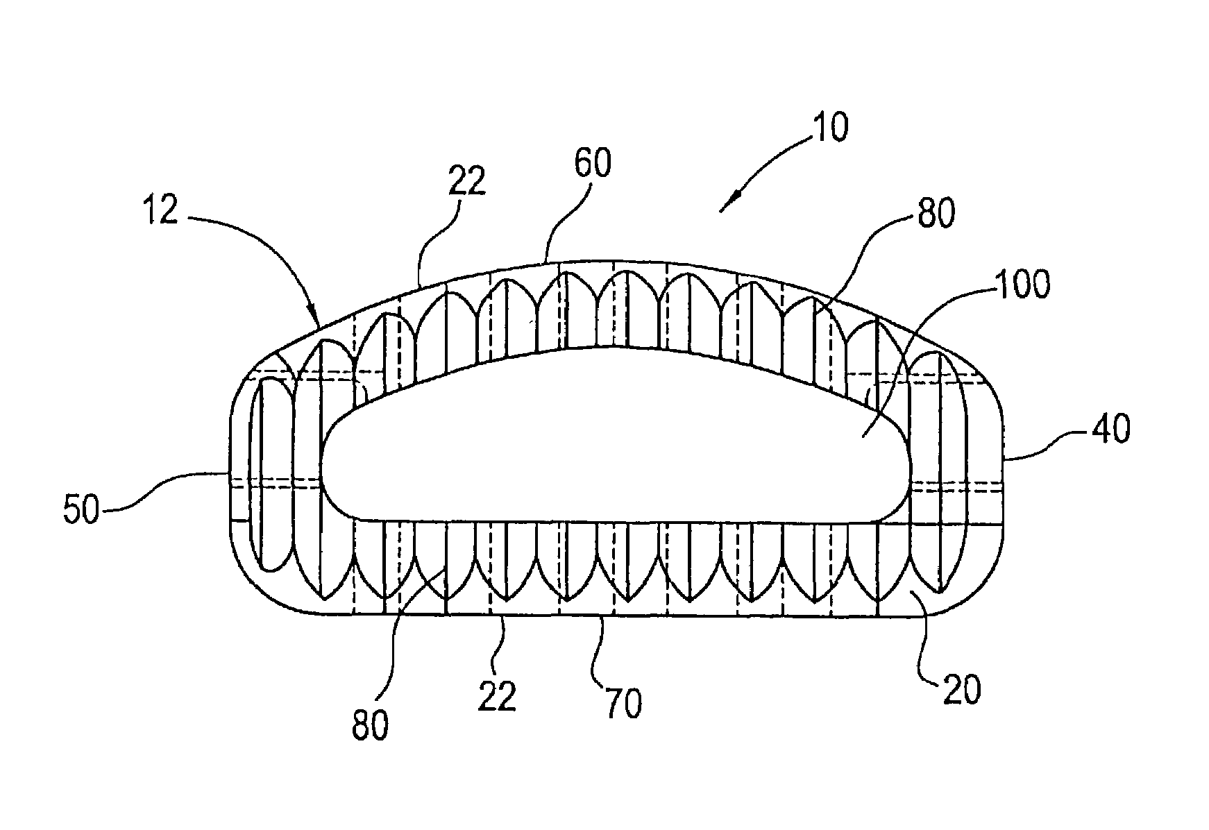
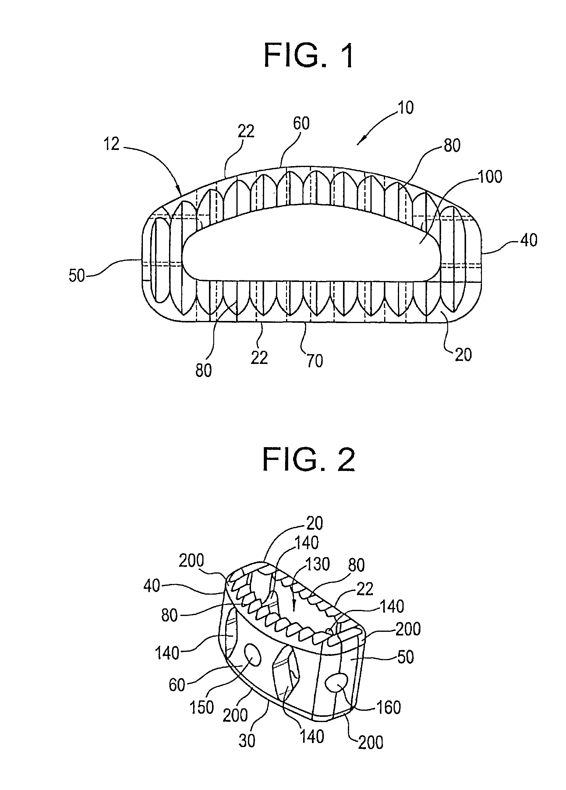
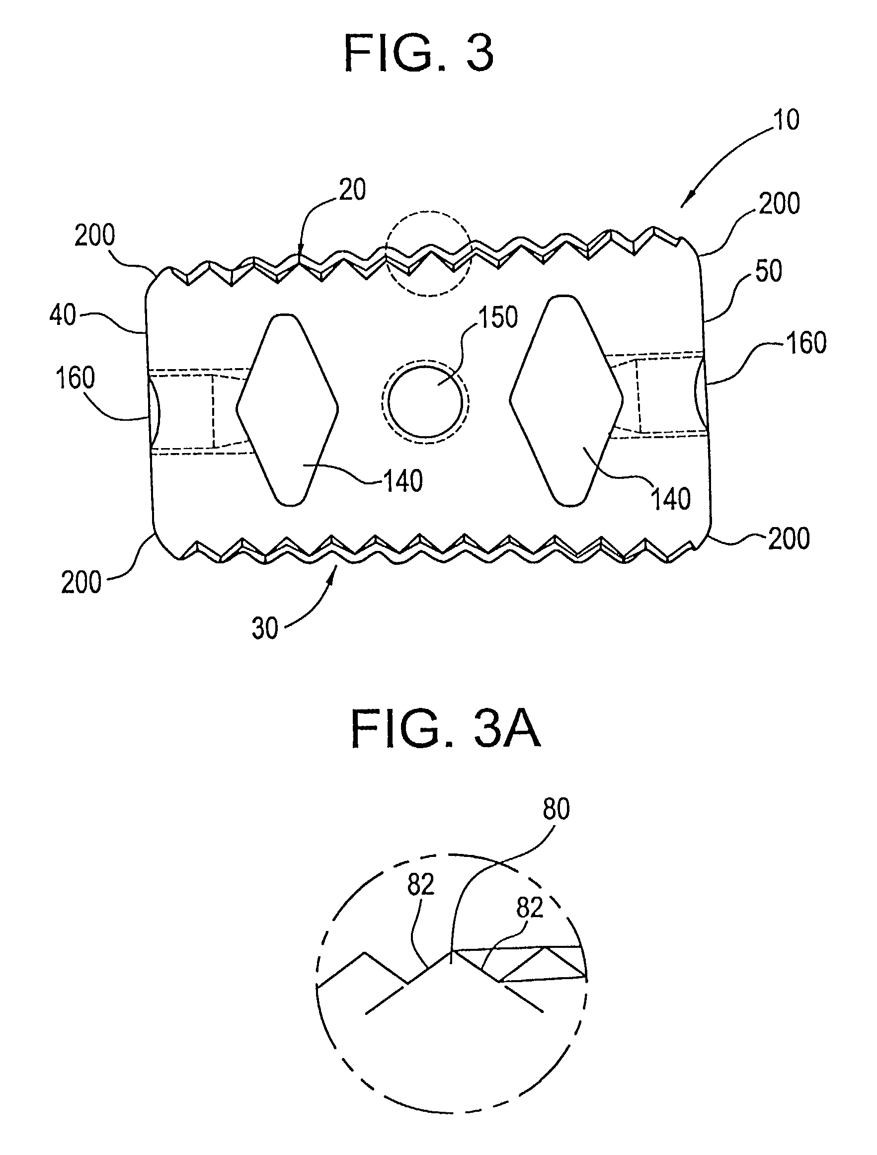
[0051]Referring to the drawings, wherein the showings are for the purpose of illustrating the preferred embodiment of the invention only and not for the purpose of limiting same, FIGS. 1–3 illustrate a prosthetic device or implant 10 which is designed to be inserted in an intervertebral disk space between two vertebrae of the spinal column. Prosthetic implant 10 is illustrated as being a cage-like structure 12 having a top wall 20, a bottom wall 30, a front end wall 40, a back end wall 50, a first side wall 60, and a back side wall 70. As best illustrated in FIGS. 1 and 2, the top wall 20 includes a plurality of ridge structures 80 which are positioned along the longitudinal length of prosthetic implant 10. As illustrated in FIG. 3, ridge structures 80 are also included on bottom wall 30. The ridge structures can be cut into the top and bottom walls and / or be formed by a molding process. The ridge structures are designed to bite into and / or readily form a rigid contact with the unde...


PUM


Abstract

An improved prosthetic implant for forming a rigid structure between adjoining vertebrae in a spinal column. The prosthetic implant includes a cage having a top, bottom, front end, back end, first side and second side walls. The first side wall has an arcuate surface. The top and bottom wall include one or more ridges to engage a surface of an adjacent vertebrae. The top and bottom wall also include an opening to receive packing material such as medicine, human tissue and the like. The top and bottom walls also incline simultaneously in two directions.

Description

[0001]This patent application is a continuation of U.S. application Ser. No. 09 / 841,924 filed Apr. 25, 2001, now U.S. Pat. No. 6,676,703 which in turn is a continuation of U.S. application Ser. No. 09 / 494,645 filed Jan. 31, 2000, now U.S. Pat. No. 6,245,108 issued Jun. 12, 2001, which in turn claims priority of U.S. Provisional Application Ser. No. 60 / 121,705 filed Feb. 25, 1999 entitled “Spinal Fusion Implant.”[0002]The present invention pertains to prosthetic implants and more particularly to inner body spinal prosthetic implants to fuse two or more vertebrae together.INCORPORATION BY REFERENCE[0003]U.S. Provisional Application Ser. No. 60 / 121,705, filed Feb. 25, 1999 entitled “Spinal Fusion Implant” is incorporated by reference.BACKGROUND OF THE INVENTION[0004]The human spine is made up of a column of thirty-three bones and their adjoining structures. The vertebrae near the head are known as the presaccral vertebrae which are separate bones capable of individual movement. The bod...

Claims


Application Information

Patent Timeline
IPC IPC(8): A61F2/44A61F2/30A61F2/00A61F2/28A61F2/46
CPCA61F2/4455A61F2/30965A61F2/442A61F2/4611A61F2002/2835A61F2002/30151A61F2002/30187A61F2002/30774A61F2002/30787A61F2002/30904A61F2002/4475A61F2002/448A61F2230/0017A61F2230/0034A61F2310/00017A61F2310/00023A61F2310/00029Y10S606/908Y10S606/91Y10S606/909Y10S606/911Y10S606/912A61F2002/30593
Inventor BISCUP, ROBERT S.
Owner DEPUY ACROMED INC
Why Eureka
Try Eureka