Method and a device for measuring, by photo-spectrometry, the concentration of harmful gases in the fumes through a heat-producing plant

Inactive Publication Date: 2007-06-12
CHLOROUT AB
View PDF2 Cites 19 Cited by
  • Summary
  • Abstract
  • Description
  • Claims
  • Application Information

AI Technical Summary

Benefits of technology

[0005]The present invention aims at overcoming the shortcomings associated with previously known measuring technique and in a purposeful way eliminating or counteracting the corrosion and deposit problems that arise in tube-including devices for heat transfer, e.g., superheater devices, economizers or air pre-heaters that exist downstream of the combustion space in combustion plants. Therefore, a primary object of the invention is to create a process as well as a device which in practical operation at difficult external conditions manage to specifically determine the presence and concentration of exactly those gaseous substances in the flue gases of the combustion process which give rise to serious corrosion or harmful deposits on the tubes that are included in said devices. Another object is to provide a process, by means of which the very creation of corrosive or harmful gases in the flue gases that shall pass through the tube devices may be restrained.

Problems solved by technology

However, it has turned out that the combustion of bio-fuel is a process that in some respects is more complicated and difficult to handle than the combustion of other solid fuels, such as coal.
One complication is that the ashes from a bio-fuel has another composition and other melting properties than, e.g., coal ash.
Inter alia, this difference involves costly problems with corrosion and ash deposition on the tubes included in existing superheating plants.
Thus, serious high temperature corrosion has been observed in the major part of combined power and heating plants in Sweden after some years of operation with 100% bio-fuel.
The problems may become particularly accentuated when to the fuel are added such materials as demolition timber and sorted waste of different types.
In practice, the corrosion manifests itself in that the usually high-alloyed, and thereby expensive, superheater tubes are coated with stout, strongly adhering layers or deposits of ash, at the same time as the tube surface underneath is exposed to corrosive melts which give rise to a loss of metal.
Thereafter, a reaction with sulphur takes place on the tube surface in the ash deposit, thereby forming potassium sulphate and free chlorine, which in this form is very corrosive.
Albeit this theory is plausible, in practice great difficulties exist not only to verify this theory but also to take measures to solve the problem, above all due to the lack of a suitable measuring technique.
Quite generally, in heat-producing plants occur, besides the above-mentioned corrosion problems, also other similar problems that are caused by the presence of gaseous metal chlorides or metals in elementary form.
When metals, such as heavy metals in the form of zinc and lead in gaseous form, are carried by the flue gases and hit the arrangements, they are deposited on the surfaces of the tubes, thereby forming deposits that are not necessarily corrosive, but that deteriorate the heat transfer from the flue gases to the medium that circulates within the tubes.

Method used


Image

  • Method and a device for measuring, by photo-spectrometry, the concentration of harmful gases in the fumes through a heat-producing plant
  • Method and a device for measuring, by photo-spectrometry, the concentration of harmful gases in the fumes through a heat-producing plant
  • Method and a device for measuring, by photo-spectrometry, the concentration of harmful gases in the fumes through a heat-producing plant

Examples


Embodiment Construction

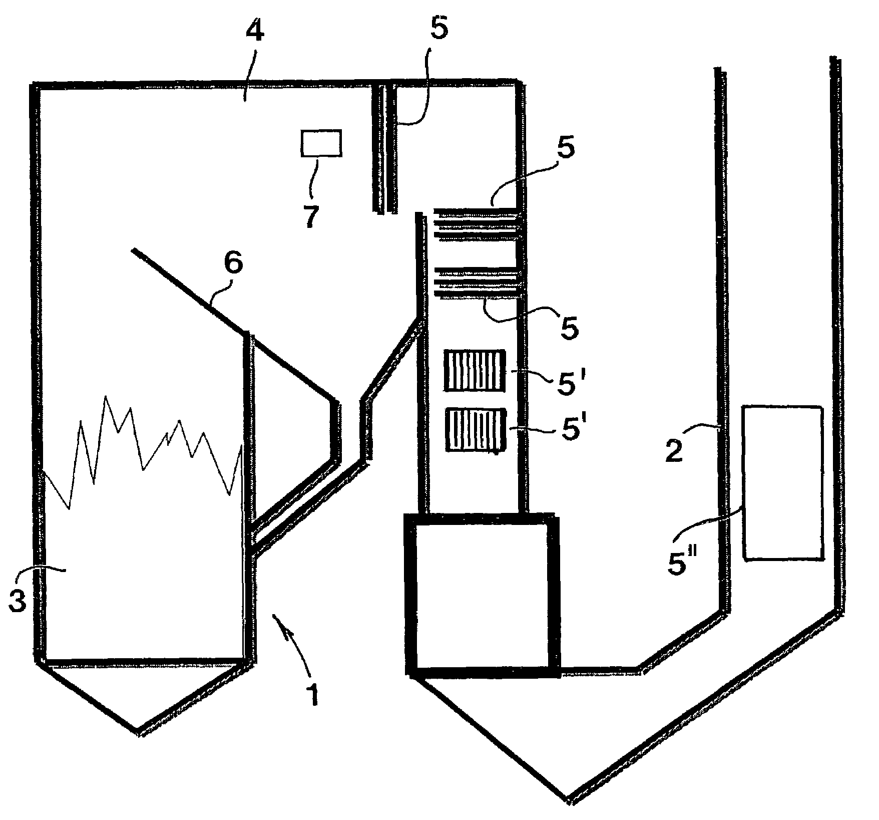
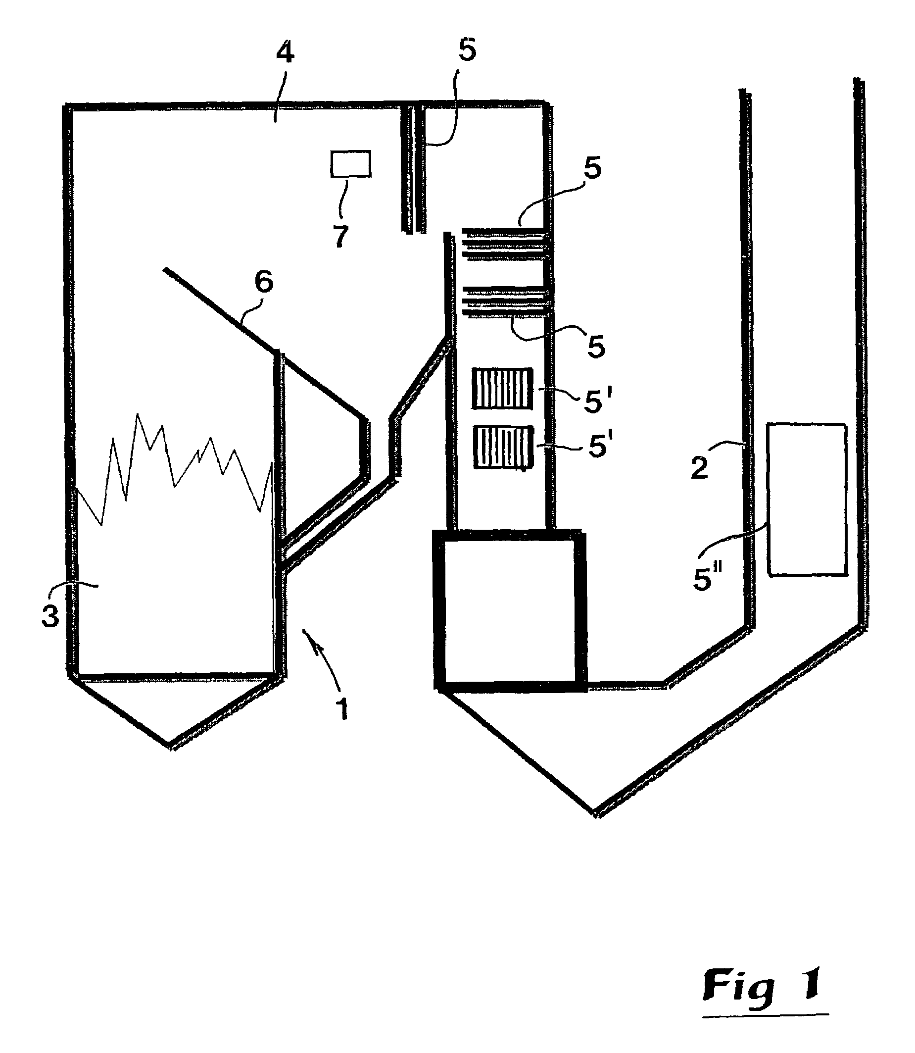
[0012]In FIG. 1 is shown a steam-producing combustion plant that may consist of an industrial steam boiler with the main purpose of producing steam, e.g., for the production of electricity, but that may also consist of a combined power and heating plant of the type that produces not only steam but also heat. As main components, the plant comprises a boiler 1 and a chimney 2. In the boiler 1 is included a first space 3 in the form of a combustion chamber, in which fed-in fuel is burnt. In practice, the boiler may work with conventional fluidized bed technique (among experts called BFB=“Bubbling Fluidized Bed”). In larger plants, the boiler may have a height within the range of 10 to 40 meters. In another space 4 serving as a flue gas duct, downstream of the combustion chamber 3, are provided one or several superheater devices. In the example according to FIG. 1, three such superheater devices 5 are shown. Each one of these devices comprises a set of tubes or tube loops, through which...


PUM


Abstract

A method for measuring the concentration of harmful gases in flue gases through a heat-producing plant that includes a combustion space and a device located downstream of the combustion space, the device includes tubes, through which for instance water, steam or air may pass in order to be heated by heat transfer from flue gases formed during the combustion. In a region near the tube device, at least one beam of ultraviolet light is emitted from a light emitter at one side of a flue gas duct to a light receiver located at the opposite side of the duct, which light emitter is connected to a spectrometer cooperating with a computer unit, in which spectrometer the light is divided spectrally.

Description

TECHNICAL FIELD OF THE INVENTION[0001]The present invention relates to a method and a device for measuring, by photo-spectrometry, the concentration of harmful gases in the flue gases through a heat-producing plant of the kind that comprises a first space for the combustion of a fuel, a device placed in a second space located downstream of the combustion space, said device in the second space comprising tubes through which a medium, such as water, air or steam, may pass in order to be heated by heat transfer from the flue gases formed during the combustion, and a chimney located downstream of the tube device for letting out the flue gases from the plant.BACKGROUND OF THE INVENTION AND PRIOR ART[0002]Simultaneous production of heat and steam by combustion of a so-called bio-fuel, i.e., a solid fuel consisting of wood or biomass, has lately become more and more common, inter alia due to the facts that such a production is power-efficient, shows endurance in the long run, may be based ...

Claims


Application Information

Patent Timeline
IPC IPC(8): G01N31/00G01N21/27F23B90/00F23G5/46F23G5/50F23J7/00F23J15/00G01N21/33
CPCG01N21/33Y10T436/18Y02E20/12
Inventor ANDERSSON, CHRISTER
Owner CHLOROUT AB
Why Eureka
Try Eureka