Wake-up reset circuit draws no current when a control signal indicates sleep mode for a digital device

Active Publication Date: 2007-06-12
MICROCHIP TECH INC
View PDF15 Cites 14 Cited by
  • Summary
  • Abstract
  • Description
  • Claims
  • Application Information

AI Technical Summary

Benefits of technology

[0007]The invention overcomes the above-identified problems as well as other shortcomings and deficiencies of existing technologies by providing a wake-up reset (“WUR”) circuit that draws substantially no quiescent current while a digital device associated therewith is in a sleep mode. Thus, the present invention draws a minimum amount of power so as not to be detrimental to the useful operating time of a limited energy storage power source, e.g., battery, capacitor, inductor, solar cell, fuel cell, etc., operated system. In addition, the present invention operates for its intended purpose even when the power source (PS) is at a low voltage that may cause meta-stable conditions in the digital device. The PS may be a discharging battery and / or a battery being replaced by the user, an energy storage device such as a capacitor or an inductor being discharged, a solar cell in a shadow, etc. In addition, the present invention also may reliably function in electrically noisy environments.
[0012]In addition to a wake-up condition, the WUR circuit can be activated by a signal transition on a dedicated WUR input. For reliable WUR operation, the circuitry to this WUR input is designed such that no sequential circuit element, e.g., flip flop, latches, etc., can disable the signal path to enable the WUR circuit.

Problems solved by technology

Other problems inherent with POR and / or brown out circuits are proper operation when a power source is below a critical voltage such that the digital logic circuits may be in unpredictable “meta-stable” states, and in applications in electrically noisy environments.

Method used


Image

  • Wake-up reset circuit draws no current when a control signal indicates sleep mode for a digital device
  • Wake-up reset circuit draws no current when a control signal indicates sleep mode for a digital device
  • Wake-up reset circuit draws no current when a control signal indicates sleep mode for a digital device

Examples


Embodiment Construction

[0021]The invention performs a wake-up reset of a digital device, having sleep and wake-up modes of operation, whenever a wake-up signal is received by the digital device (e.g., a digital processor, microcontroller, microprocessor, application specific integrated circuit (ASIC), programmable logic array (PLA), digital signal processor (DSP), etc.).

[0022]Referring now to the drawings, the details of specific embodiments of the present invention are schematically illustrated. Like elements in the drawings will be represented by like numbers, and similar elements will be represented by like numbers with a different lower case letter suffix.

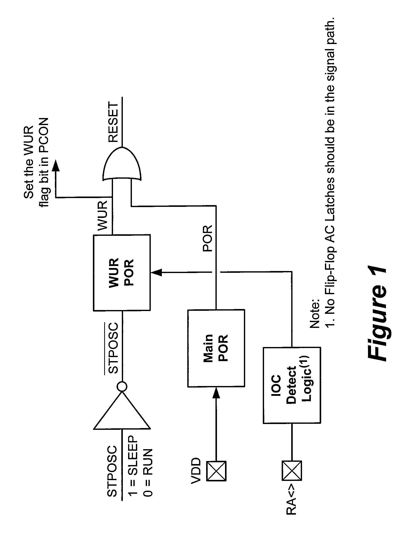
[0023]Referring now to FIG. 1, depicted is a schematic logic block diagram of a specific exemplary embodiment of the invention. The wake-up reset (“WUR”) module, generally represented by the numeral 100, comprises wake-up reset (“WUR”) circuit 102, main power on reset (POR) 104 and an OR-gate 108. Optionally, an inverter 110 may be used for inverting...


PUM


Abstract

A wake-up reset circuit is provided that generates a reset signal to a digital circuit upon a wake-up event. The wake-up reset circuit places the digital circuit into a known reset condition upon wake-up, even if a brown out condition occurs which may have caused unstable and unknown logic states in sequential circuit elements, e.g., volatile memory, flip flops and / or latching circuits. The wake-up reset circuit draws substantially no current when not generating the reset signal.

Description

RELATED PATENT APPLICATION[0001]This non-provisional patent application claims priority to commonly owned provisional patent application USSN 60 / 532,323, filed Dec. 23, 2003, entitled “Wake Up Reset Circuit” by Hartono Darmawaskita, Layton W. Eagar, Ryan Scott Ellison and Vivien Delport, and is hereby incorporated by reference herein for all purposes.BACKGROUND OF THE INVENTION TECHNOLOGY[0002]1. Field of the Invention[0003]The present invention relates generally to digital electronic circuits. More specifically, the present invention relates to wake-up reset circuits that generate integrated circuit (“chip”) reset upon a wake-up event.[0004]2. Background of the Related Technology[0005]Electronic circuits have been used to monitor the voltage of a power source to an electronic device in order to detect a required voltage threshold in generating a power on reset (“POR”) for the electronic device. The same or other circuits have been used to detect a brown out or power down condition....

Claims


Application Information

Patent Timeline
Patent Type & Authority Patents(United States)
IPC IPC(8): G06F1/26G06F1/24H03K17/22
CPCG06F1/24H03K17/22
Inventor DARMAWASKITA, HARTONOEAGAR, LAYTONELLISON, RYAN SCOTTDELPORT, VIVIEN
Owner MICROCHIP TECH INC
Why Eureka
Try Eureka