Medical cock

a stopcock and sealing technology, applied in the direction of valve details, valve arrangements, other medical devices, etc., can solve the problems of insufficient sanitary procedures, difficult to wipe off the remaining solution and sterilize the tube, and the end region of the tributary tube is prone to microbial contamination, so as to reduce the length of the flow passage, facilitate the process, and prevent the effect of entry

Inactive Publication Date: 2007-06-19
NIPPON SHERWOOD MEDICAL IND LTD
View PDF9 Cites 75 Cited by
  • Summary
  • Abstract
  • Description
  • Claims
  • Application Information

AI Technical Summary

Benefits of technology

[0021]The present invention not only prevents entry of bacteria into the infusion fluid during administration of the primary drug solution through the main conduit but also significantly facilitates processes including collection of blood samples and removal of air bubbles because of the reduced length of the flow passage. Also, the present invention allows the valve body to be rotated during mixed infusion or side injection to switch from one flow passage to another with the sharp needle or the blunt needle placed through the septum and remaining within the switching channel. Accordingly, a highly operable sealable access stopcock is achieved. Further, the present invention, which includes limitation means for limiting the range of rotation of the valve body as well as click means for stopping rotation of the valve body in a discrete manner, provides a safe, manageable sealable access stopcock.
[0022]The present invention achieves a sealable access stopcock that facilitates switching of the flow passage of infusion fluid as well as removal of air bubbles, has good isolation property for preventing microbial contamination, and is easy to operate to introduce a drug solution into a blood vessel while preventing stagnation of the drug solution.

Problems solved by technology

Accordingly, there is a risk of microbial contamination from the end region of the tributary tube 7.
In addition, the deep hollow construction of the tributary tube 7 makes it difficult to wipe off the remaining solution and sterilize the tube, which often results in insufficient sanitary procedures.
For this reason, once bacteria enter the tributary tube 7, it is extremely difficult to prevent their growth.
This increase in the volume of the flow passage of infusion fluid leads to formation of a dead space in which a small amount of the high concentration drug solution remains.
As a result, dosage of the drug solution may fall short, or the drug solution may be wasted.
Furthermore, if administration of an additional drug solution follows, the residual solution may be added to the additional solution, which results in an excessive dosage or a mixture of the added drug solution and the residual solution being administered to patients.
This is a particularly serious problem in the case of arterial infusion, in which blood collection is essential.
Further, the increased passage length increases generation of air bubbles 40 and makes it considerably difficult to remove the bubbles.
In addition, such a dead space makes the deaeration process difficult during the brimming process when the infusion passage is filled with infusion fluid in the first place.

Method used


Image

  • Medical cock
  • Medical cock
  • Medical cock

Examples


first embodiment

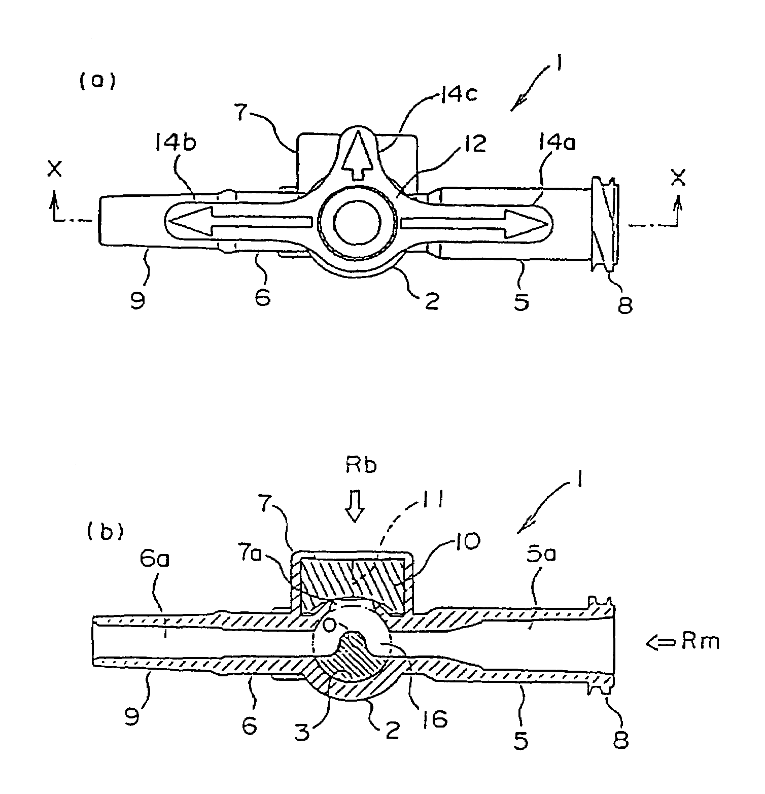
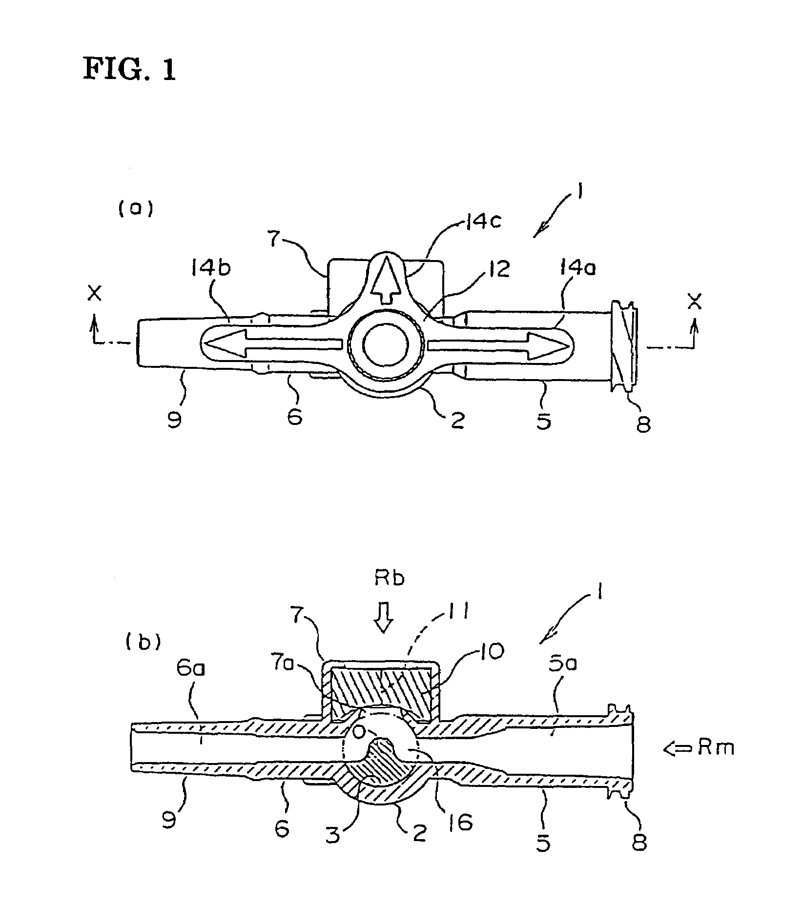
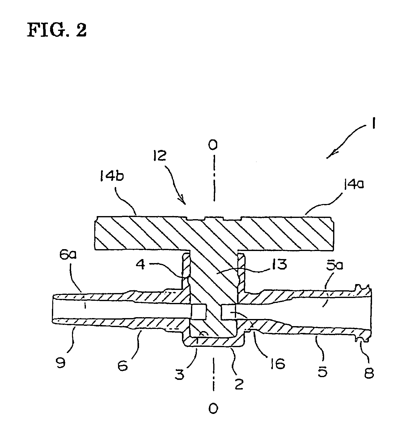
[0037]FIGS. 1(a) and 1(b) are schematic diagrams showing construction of a first embodiment of the present invention, where FIG. 1(a) is a frontal view; and FIG. 1(b) is a cross-section thereof. FIG. 2 is a cross-section taken along the line X—X in FIG. 1(a). FIGS. 3(a)–3(e) are schematic diagrams showing construction of a valve body according to the first embodiment, where FIG. 3(a) is a top view; FIG. 3(b) is a plan view; FIG. 3(c) is a frontal view; FIG. 3(d) is a right-side view; and FIG. 3(e) is a cross-section taken along the line Y—Y in FIG. 3(a).

[0038]Referring to FIGS. 1 and 2, a reference numeral 1 denotes a sealable access stopcock and a reference numeral 2 denotes a main body formed as a bottomed cylinder. The main body 2 is made of a transparent resin material such as polycarbonate (PC) and polyethylene terephthalate (PET) and PET / PC alloys. A reference numeral 3 denotes an internal chamber centered on a central axis O—O. A reference numeral 4 indicates an annular groov...

second embodiment

[0051]FIG. 8 is a cross-section of one construction of a second embodiment of the present invention showing major components thereof while FIG. 9 is an enlarged cross-section taken along the line Z—Z in FIG. 8.

[0052]In FIGS. 8 and 9, a reference numeral 30 denotes a limitation tube placed about the valve shaft 13 of the valve body 12, a reference numeral 31 denotes a limitation projection projecting from the inner surface of the limitation tube, and a reference numeral 32 denotes an arcuate cutout formed along the outer periphery of the main body 2 at the top end thereof. The angle of the cutout 32 formed on the main body 2 is substantially the same as the above-described angle θ of the arch of the switching channel 16. The limitation projection 31 on the valve body 12 engages the cutout 32.

[0053]When the valve body 12 is turned through the handles 14a and 14b to switch from one flow passage to another, the limitation projection 31 slides within the arcuate cutout 32. The valve body...

third embodiment

[0054]Referring to FIG. 10, major components of a third embodiment are shown in an enlarged perspective view. This embodiment employs a construction featuring a click function for causing the valve shaft to snap into position at different positions, in addition to the above-described function of the second embodiment for limiting the rotation angle.

[0055]In FIG. 10, a reference numeral 33 denotes a slit formed on either side of the limitation projection 31, which was described in the second embodiment above. A reference numeral 34 denotes a semicircular protrusion. The slits 33 allow the limitation projection 31 to resiliently move in the radial direction with respect to the central axis O—O. Accordingly, the protrusion 34 can be resiliently displaced in the radial direction.

[0056]Though not shown, the cutout 32 of the main body 2 shown in FIG. 9 includes three axial grooves each having a semicircular cross-section that corresponds to the protrusion 34. The grooves are formed at thr...


PUM


Abstract

A sealable access stopcock includes a valve body having a switching part formed in a valve shaft thereof for switching from one flow passage to another; and a main body having an internal chamber in which the valve shaft of the valve body is rotatably fitted, and a plurality of tributary tubes each having a lumen extending therethrough, the lumen opening on a side wall of the internal chamber; the valve body being rotated to selectively bring the lumens into communication with one another through the switching part and thereby switch flow of an infusion fluid from one flow passage to another. A switching channel is provided in the form of an arcuate groove in the switching part of the valve shaft to extend along the circumferential surface thereof.

Description

TECHNICAL FIELD[0001]The present invention relates to a sealable access stopcock. More particularly, the present invention relates to a sealable access stopcock including a plurality of tributary tubes for connecting an infusion tube and a switching part for switching from one flow passage to another. Such a stopcock is provided on a flow passage of infusion fluid to allow mixed infusion of an additional drug solution by switching the flow passage, or a syringe may be connected to the tributary tube through its needle to inject another drug solution or to collect a blood sample by switching from one tributary tube to another as desired.BACKGROUND ART[0002]3-way stopcocks are known as one type of such medical instruments. A 3-way stopcock includes three tributary tubes that are separated from one another by an angle of, for example, 90°. FIGS. 11(a) and 11(b) shows construction of the conventional 3-way stopcock while FIGS. 12(a)–12(b) and 13(a)–13(b) each illustrates one application...

Claims


Application Information

Patent Timeline
Patent Type & Authority Patents(United States)
IPC IPC(8): A61M5/00F16K35/00A61M39/00A61M39/02A61M39/22F16K11/076
CPCA61M39/02A61M39/223
Inventor INUKAI, KAZUAKIMIYASAKA, SUSUMUABE, KAZUHIROMAKINO, HIDEYUKI
Owner NIPPON SHERWOOD MEDICAL IND LTD
Why Eureka
Try Eureka